

3D printing is quickly transforming from a method for prototyping and making tooling into a technology for manufacturing end parts.
GE has just snapped up metal systems producers, and large manufacturers like Adidas and Oracle are using Carbon’s platform for end production. As 3D printing is incorporated into the larger manufacturing workflow, there will be plenty of issues to address.
In addition to workflow management concerns, such as those that SAP is attempting to solve, there is the problem of characterizing the additive manufacturing (AM) process. In many cases, AM systems can be difficult to control or predict, particularly when making a part the first time around. A component’s orientation and shape will completely change the nature of the printing process and the part’s ultimate performance. As a result, it may require multiple attempts to print an object before achieving the proper result.
One answer to these problems and more may be the use of simulation software, both for its use in characterizing the printing process itself and for predicting the performance of the part once it comes out of the printer. So far, there are few companies working to engineer simulation software for AM. One of the few is the recently acquired simulation company MSC Software, which has developed Digimat Additive Manufacturing (Digimat-AM) and Simufact Additive software for polymers and metals, respectively.
Simulating for 3D Printing
Both metal and plastic AM have their issues. With metal, parts can become distorted during the printing process and residual stresses may cause part or support failure during a print. Occasionally, a powder scraper will collide with a part and cause damage to the machine. Even successful prints must meet specifications related to porosity and microstructure.
In plastics, parts may warp or fail. With fused deposition modeling (FDM), bed adhesion may be an issue, with the initial layers of the print not sticking to the bed properly. For both technologies, the approach so far has been based on trialanderror, by modifying the print parameters or design until the print is successful.
To address these issues, MSC looked to physics-based simulations to optimize the materials, processes and structure for metal and polymer AM with the goal of enabling proper prints with the very first print. To do so, the company’s Simufact Additive and Digimat-AM software are designed to optimize the print materials, process and the structure of the designs themselves.
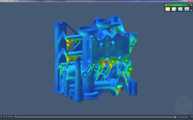
Both platforms use a layer-based voxel approach to simulating the printing processes, which provides a macro-level look that is much quicker to run than finite element analysis (FEA). As you can see in the video below, a digital model is represented as a stack of cubes enmeshed by an outer surface. As it simulates a printing process one full layer at a time, the software calculates the difference between the voxels as they will be printed and the part surface, determining how much the surface will be filled with the voxels.
Simulating for Metal
Simufact Additive is designed specifically for powder bed metal AM processes, such as selective laser melting and electron beam melting. For directed energy deposition processes, MSC suggests that its Simufact Welding software can be used.
Simufact Additive relies heavily on the concept of inherent strain, already utilized in welding, to determine the strain—creep strain, thermal strain, phase transformation strain and others—placed on a part during the metal 3D printing process.
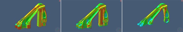
To determine the inherent strain of a metal AM system, the operator fabricates three cantilever beams that are oriented horizontally, vertically and at an angle. The beams are then cut in half, causing them to bend upward. The displacement of the tip of the beam from the flat surface is then measured and the result is plugged into the software, which determines the inherent strain of the machine. The video below shows how a part would be distorted during a printing process.
Once this data is stored in a user’s database, it’s possible to run a variety of simulations, including how heat treatment will affect the part, part removal and the effects of hot isostatic pressing (HIP). With heat treatment, material properties are a function of temperature. Using the software’s built-in materials database, a metal’s performance characteristics—elastic modulus, young’s modulus, flow stress, conductivity, etc.—are incorporated into the digital model as it is virtually exposed to heat.
With HIP, the same variables are taken into account and the physics of pressure is added. The software is able to determine the additional stress and distortions made to the part as it is placed under high pressure. This will be essential to understanding the density and porosity of the part as it is pressed.
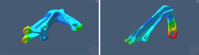
After performing a number of simulations, such as the strain placed on a part during printing or the densification caused by HIP, a user can redesign a part to compensate for such issues. For instance, if it’s known that a component’s thin walls will deform while being printed, the walls can be made thicker.
A user might also decide to choose a specific orientation in the printbed to minimize stress on one area of the design over another. This might expand to the placement of support structures, which can be located minimally and only where they are most needed to reduce the amount of support removal after the part is complete.
To validate the software’s capabilities, MSC partnered with the Fraunhofer Institute for Machine Tools and Forming Technology and NTT Data. The partners produced several parts and compared them to simulations made in Simufact Additive, and found that such issues as part distortion and failed support structures were captured accurately.
In the future, the software will also be able to perform meso- and microscale analyses of a part before it is printed.
Read more at ENGINEERING.com