
Additive Manufacturing (AM) has made a splash as the technology for producing highly customized products in almost any material you can think of. Thanks to design flexibility, 3D printed metal parts can be produced for every application from aerospace to medical.
However, AM’s unique designs come with a hitch.
Freshly printed metal parts require extra machining steps to remove structure supports, and the rough surface finish and unreliable dimensional accuracy of some additive processes can make precision features such as mating surfaces and tapped holes impossible. Because complexity is free with additive manufacturing and parts need not conform to conventional orthogonal shapes, customized parts may also come in shapes that make workholding especially challenging.
This article will review how manufacturers today can overcome some of these challenges and optimize their AM processes.
Why Metal for Additive Manufacturing?
AM is an ideal process for metal as it allows metal parts to be built without the need for conventional tooling, ignoring many geometric limitations, and allowing for part consolidation for more efficient designs. This makes several metal alloys ideal materials for aerospace, automotive and medical applications as well as improves productivity in injection molding and expands possibilities in creative industries such as architecture.
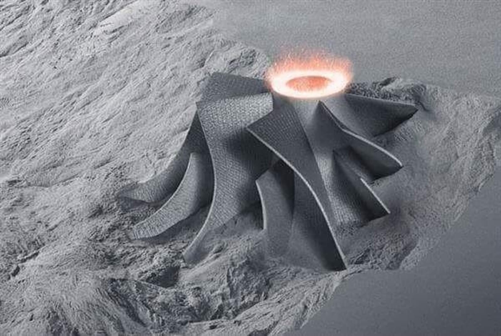
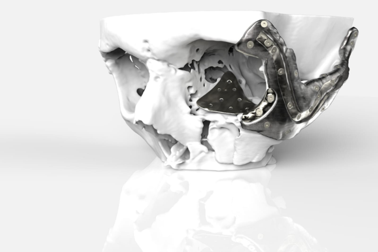
Metals that are particularly suited to welding and casting are ideal for 3D printing. Conversely, metals that are difficult or costly to cut and machine are also ideal for AM. Some of the most popular metals used include titanium, aluminum, stainless and tool steels, Inconel, copper and tungsten.Titanium is highly popular in aerospace and medical applications for its lighter weight. With internal lattice structures, implants can be designed to accommodate bone ingrowth. Steel, on the other hand, can be used to print strong parts which are able to withstand extreme environments, such as combustion or high holding pressures. These and other metals can be printed from powder or melted wire.
Metal AM can be performed with several techniques including Selective Laser Sintering (SLS) for powder beds, Laser Metal Deposition (LMD) for either powder or wire, and Wire Directed Energy Deposition (WDED).
SLS is popular for creating smaller parts with more complicated designs using a “build-up” technique, which fuses metal powder using a CO2 laser along an X and Y axis, over a descending tray in a sealed, inert gas environment. A roller evens out the bed as the tray descends before the next pass of the laser.
WDED uses lasers to melt wire fed through a nozzle, usually in a sealed gas enclosure. This method achieves higher deposition rates compared to SLS, but can suffer from lower resolution. WDED is popular in applications requiring simpler parts and where conventional manufacturing techniques are slow or expensive, like in aerospace and automotive.
With such techniques, AM can provide significant cost and time savings for difficult to manufacture parts, while also allowing for more complex, smaller batch parts. AM has its fair share of weaknesses, however.
Extra Machining Steps Often Necessary for Metal 3D Printing

To put it bluntly, 3D printing metal parts is often not the solution for a manufacturer looking to produce parts at a high, mass-production volume. AM is ideal for smaller batch productions that emphasize customization and unique design over sheer quantity. Unfortunately, even the great degree of design flexibility causes its own issues.
Printed metal parts don’t come out of the machine with a smooth surface, and are often made in such unique shapes as to require support structures to help keep the part upright and stable during the printing process. As a result, extra machining steps are necessary in order to remove support structures and perform surface finish procedures.
Removing supports may require manual processes such as using a bandsaw, and deburring may be necessary for certain parts, especially for applications which may not require machining, says Mark Kirby, additive manufacturing business manager at Renishaw Canada.
“The only time we don’t do machining is, ironically, on some medical parts like cranial plates which will be polished,” says Kirby. “We’ll have a lot of manual work to do to make them smooth.”
If a part requires holes, it is often better to drill them afterward than print them with the holes, to prevent rough surfaces in these negative spaces which can often come out at improper measurements.
While certain non-critical hole features Kirby suggests are acceptable to print with good datum points, anything large in size or especially precise is likely more trouble than it’s worth.
If a printed hole is out of position, it could demand a time-consuming manual fix, Kirby explained. “I might have to helically interpolate it and put it on a center where it needs to be and so on. If I just drilled it, it would have been in the right position.”
Furthermore, printed holes could be inconveniently placed on the part and hard to reach for machine tools during the finishing process.
Parts with unconventional shapes cause additional challenges when it comes to workholding. During the finishing process, a part may need to be held at odd angles, requiring the manufacturer to have a good understanding of where the work piece will relate to the cutting tool and how it will interface with the table of the machining center.
Clamps and vices are usually the first go-to workholding solution, but such options are ineffective for 3D printed parts with complex geometries.
For more complex and delicate parts, soft jaws are a good solution as they can be contoured to more accurately fit the part. These soft jaws could be 3D printed themselves. Kirby finds these solutions effective, but smaller printed parts, such as those for medical applications, are not typically designed with load tolerances able to withstand machining.
Keeping these limitations in mind is essential when considering machining techniques and proper workholding solutions.
Read more at ENGINEERING.com