

It’s no fun to get a part or assembly ready for simulation.
You have to spend hours eliminating details that, if left in, would choke the solver with a ridiculous number of tiny elements. It’s tedious and time consuming. Then you request a mesh and cross your fingers. Being conscientious, you probably check the mesh, because you know not all meshes are created properly.
This two-step process, first simplifying the model and then meshing it, accounts for most of an engineer’s time spent on simulation. In fact, studies have shown that this accounts for up to 70 percent of the time spent in FE modeling and analysis.
Engineering.com readers are familiar with SimSolid, which provides an alternative to traditional finite element analysis methodology. SimSolid does not require model simplification or meshing. Instead, SimSolid uses a proprietary mesh-free method, which works directly on the original CAD geometry.
“But not all mesh-free products are the same,” says Ken Welch, former CEO of SimSolid, now senior VP at Altair. “Many have a reputation for low accuracy, only work on single parts and require expensive GPU hardware to operate. SimSolid is different. It was written from the ground up to be a large assembly solver, runs on standard desktop or laptop PCs and provides accurate results in seconds to minutes.”
We catch up with Welch, co-founder of SimSolid, after the larger simulation vendor Altair acquired his company last October. Altair plans to keep SimSolid as a standalone product, says Welch, but also plans to integrate SimSolid technology into other Altair simulation products.
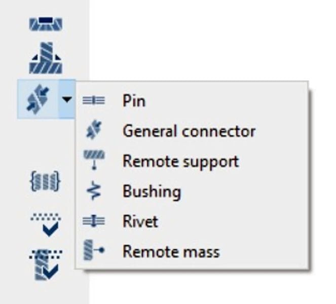
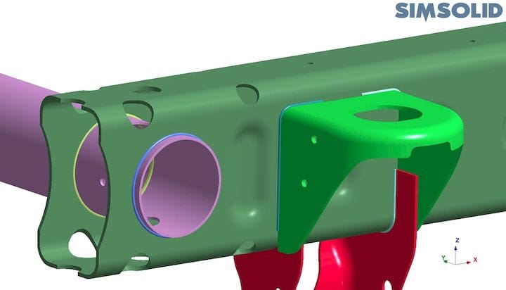
Altair SimSolid shines bright with assemblies, and even brighter with recent releases, as it now provides an expanded set of advanced fasteners such as bolts, welds, rivets and bushings. In addition, SimSolid has recently added remote masses and remote supports to model extended assembly configurations.
Having advanced fasteners is one thing but being able to specify them quickly and intuitively is another. “Since SimSolid only works on full 3D CAD geometry, fasteners are easier to apply, and this is extended further by several automation workflows. With assemblies that have a large number of fasteners, the ability to handle them more or less automatically can be a huge timesaver all by itself,” says Welch.
Every Day is Weldsday
Welds are a huge pain to analyze. With your typical simulation product, an enormous number of tiny elements are required to model a weld. You might be tempted to ignore the weld, but that could be a big mistake. Often, the weld is critical. Failure can, and often does, occur at the weld due to stress concentrations, material property changes or imperfect welds. Fatigue can also play a significant part in a weld failure.
With SimSolid, weld modeling is much easier, according to Welch. CAD weld definitions, commonly represented as indicator parts consisting of solid tubes or wedges, are recognized and converted automatically.
“A single fillet weld dialog provides all necessary inputs,” says Welch. “Users simply need to specify the weld diameter and which parts to convert, or even better SimSolid can examine all parts and propose which ones are suitable to convert. Once the user verifies the selection, SimSolid will replace each CAD weld tube part with its mechanical equivalent. The original geometry representing the weld is suppressed. All welds can be created at one time using this method.”
“I’ve seen weld modeling go from weeks to minutes using this method,” Welch adds.
Read more at ENGINEERING.com


