

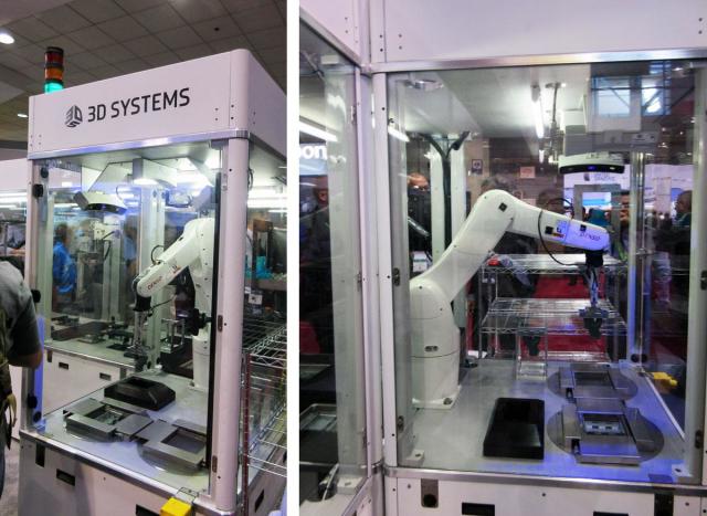
As the industrial 3D printing market shifts into fifth gear, all of the major 3D printer manufacturers are unveiling new systems best fitted for end part production. 3D Systems’ newest contribution to this space is Figure 4, a modular 3D printer that is, according to company, meant to be a factory production system.
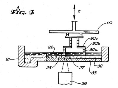
The name “Figure 4” comes from 3D Systems’ Cofounder Chuck Hull’s original 1984 patent for stereolithography (SLA) 3D printing technology. “Fig. 4” of the patent illustrates the SLA process with a light source projecting from below liquid resin and a printbed lifting the printed object up from the vat of material. Though the patent was filed 32 years ago, it was never given physical form by 3D Systems—until now.
The Figure 4 setup is an exciting one for both 3D Systems and for those in the 3D printing and manufacturing industries. After speaking with the new CEO of 3D Systems, Vyomesh Joshi, I was able to get a personal look at the machine at International Manufacturing Technology Show (IMTS) 2016.
The Speed of Figure 4
Figure 4 has some very unique features that make it stand out compared to both 3D Systems’ existing 3D printers and those from other manufacturers. To start, the system is mounted to an industrial robotic arm, with the arm lifting the printbed and printed object up from a vat of resin.
It does this very quickly through the use of a specialty membrane that sounds strikingly similar to the oxygen-permeable amorphous fluoropolymer (Teflon AF 2400) membrane patented by Carbon for the start-up’s continuous liquid interface production (CLIP) technique.
The sample part shown to us at IMTS took 22 minutes to print. After Joshi suggested that it was fast (“Wait till you see it,” he kept saying), I was expecting it to be faster. In fact, if matched up against CLIP, it is estimated to be about half as fast as Carbon’s technology.
Modular 3D Printing for the Production Line
So, it may still be slow by conventional machining standards, but the company suggests that added speed and efficiency come from the robotic arms—which did not appear to be moving any faster than a human—because many print volumes and robotic arms can be used in a single Figure 4 setup.
Robotic arms, single or multiple, are used only for pick and place (unlike the Stratasys system, which uses a 3D printhead mounted onto a robotic arm). While one arm prints an object, another can remove a completed print and implement post-processing procedures, such as secondary ultraviolet curing.
Though each resin tank measures only 3 in x 5 in x 6 in, multiple tanks can be utilized in each Figure 4 setup. More importantly, Figure 4 is scalable so that larger industrial robot arms can be used and the tank can potentially be enlarged.
Read more at ENGINEERING.com