

There’s no more need to say that 3D printing has finally “made it” in the world of industrial manufacturing. Now, it’s time to really make it work and to fully integrate it into the manufacturing supply chain.
Siemens PLM is among the large players tackling this problem and its latest product announcement is the first step in making additive manufacturing (AM) work for end production. In October, Siemens announced the development of a complete end-to-end software suite devoted to AM.
Senior Director of Marketing for Siemens PLM Software Aaron Frankel was able to speak to ENGINEERING.com about how the software giant’s AM solutions will aid in the industrialization of 3D printing.
Siemens AM
In January 2017, Siemens will begin rolling out its new software dedicated to 3D printing. These solutions will more or less attempt to address AM from every step of the design to production process, including design optimization, simulation and the actual fabrication of a part. Software in the suite will consist of:
- Siemens NX software for computer-aided design, manufacturing and engineering (CAD/CAM/CAE)
- The Simcenter portfolio for simulation and testing
- The Teamcenter digital lifecycle management system
- SIMATIC IT Unified Architecture Discrete Manufacturing and SIMATIC WinCC for managing and automating the production process
Frankel discussed the purpose of this new product suite: “Our vision is to eliminate all of these different gaps and limitations from the process so that companies, design engineers, manufacturers can all take better advantage of 3D printing and the enormous value that it can provide.”
Integral to the efficiency of this software suite is the ability to work with models without the need for converting or translating files from one program to the next. Frankel explained, “When we have to transfer or convert data between different applications, we tend to lose intelligence, and that can cause errors. It can increase the amount of time it takes to develop a product and it limits companies from using additive manufacturing in a true production setting.”
Convergent Modeling and Topology Optimization
With Siemens’ new software, the company will be introducing convergent modeling and topology optimization tools for 3D printing. Convergent modeling makes it possible for designers and engineers to work with different types of data within a single project and without the need to convert one type of model into another file type in the process. This is particularly useful for incorporating facet geometry, which relies on mesh data, into a traditional engineering workflow that uses precise geometry based on mathematical functions.
“We tend to see an increased use of faceted geometry in the design process, from scanning an existing product to create a digital representation, for example,” Frankel said. “Previously, we could then use that data to guide us in our designs, but because those shapes use facet geometry, you cannot directly model on those facets to change its shape or to add material. You basically add additional effort and work.”
However, with convergent modeling available with Siemens NX, it’s possible to work with both faceted and precise geometry within a single environment. For instance, one could directly model a 3D-printed implant using a model made with a patient’s CT scan within the same project, despite the fact that the scan would likely use mesh data and the implant design might use math-based modeling. Siemens demonstrates such a possibility in the video below.
In order to fully take advantage of 3D printing, however, it becomes important to implement topology optimization. As those familiar with 3D printing well know, the technology makes it possible to fabricate geometries not possible with traditional manufacturing techniques, including complex shapes that may be stronger and lighter weight through topology optimization.
These objects can become more organic than might have been possible with precise geometry design tools previously implemented, making it necessary to use both faceted and precise geometric modeling. The video below showcases how convergent modeling and topology optimization can be combined to create a lightweight, 3D printable object.
Simulating 3D-Printed Designs
With new technologies and geometries come new surprises, as the performance of a complex, 3D-printed geometry may be difficult to predict. With Siemens’ software, it’s possible to run physics simulations, such as residual stress or the flow of heat or liquid through a part. This not only makes it possible to see how a part will perform, but also how it might compare to a legacy part manufactured with conventional techniques.
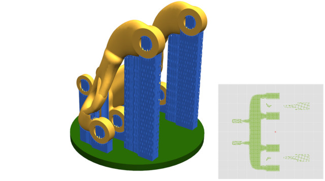
Manufacturing complex parts, however, is easier said than done, even with industrial AM technology. The orientation of a part or the placement of support structures can ultimately make or break a design. To address this issue, Siemens has developed simulation tools that predict what the printing process will look like for powder bed 3D printing and HP Multi Jet Fusion. Users can orient parts and add support structures, and then watch the part virtually printed to better understand if the print has been prepared properly.
Frankel pointed out that, with the acquisition of CD-adapco, Siemens is able to simulate a powder bed process at the microscale. Frankel explained, “We can look at how particles of powder might fill the build tray, for example, as well as how a certain laser and its power and size might affect the melting of that particular powder. With this, we can start to analyze energy transfer, residual stresses, temperature distributions, and begin to simulate and identify if we might end up with residual porosity, which could lead to poor quality, for example.”
Frankel continued, “That same train of thought could apply to validating the design of a part for a sintering process. We could look at the shape of the design and as it’s being built look at the temperature distribution of the particular laser path as it’s been designed on the part and see how that temperature distribution could result in a distortion of the part shape while it’s being built.” This would then make it possible to determine whether the print strategy should be changed or if the part would need to be altered to compensate for such distortion.
Frankel added that Siemens is also introducing new tools for design guidance that perform various checks to determine printability. “These essentially help you position the parts properly, identify whether or not you’ll be able to remove any powder that might have been captured on the interior of the part,” Frankel said. “And I see these types of design rules being extended as we learn more about the best ways to design for 3D printing.”
Read more at ENGINEERING.com