
FFF slicing has a very basic assumption built into it: every new layer should be flat.
That assumption makes a lot of sense. Flat layers are easy to calculate, easy for a Cartesian motion system to execute, and reasonably safe for the nozzle that has to avoid crashing into already-printed material.
But they also create that ugly stair-stepped surface finish on curved surfaces. You can reduce the effect with thinner layers, of course, but that slows down the entire print — including all the areas that did not need finer resolution.
A paper titled Slicer-independent generation of customizable non-planar toolpaths for fused filament fabrication suggests a more interesting solutioon: making the toolpath itself curve in three dimensions.
Non-planar FFF is not a new idea. Instead of depositing a strand along a constant Z height, the nozzle follows a path that rises and falls as it travels across a part. If that path follows the contour of a curved upper surface, the deposited filament can form a much smoother skin than a stack of flat terraces.
The most difficult challenge has always been software.
Most mainstream slicers are designed around flat planar layers. They may offer adaptive layer heights, ironing, variable extrusion widths, and other refinements, but their basic output is still a sequence of mostly horizontal slices. Producing a truly non-planar finish path usually means modifying a slicer, using a specialized research tool, or manually assembling GCODE.
None of those is especially useable for a 3D printer operator who just wants a better curved surface on a particular region of a part.
The researchers’ proposed direction is to separate non-planar path generation from the slicer itself. Rather than requiring a conventional slicer to understand every geometric detail of a curved deposition path, an external method can generate customizable motion paths and integrate them into the manufacturing workflow.
A slicer is a large and complicated piece of software. Asking every slicer developer to support a research-grade non-planar strategy is never going to become widespread. A toolpath generator that can work alongside existing slicing workflows has a much better chance of becoming an experimental add-on, a specialist finishing utility, or eventually a feature in commercial preparation software.
There is still a very physical constraint that controls all non-planar work: the nozzle is not just a point in 3D space.
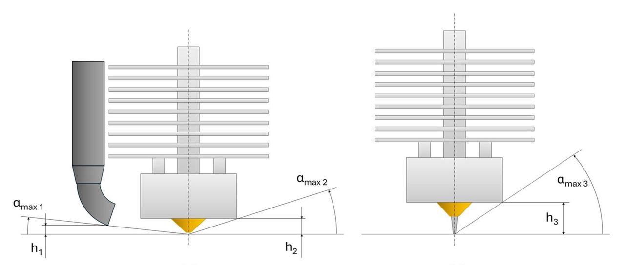
As the nozzle follows along a curved surface, its body, heater block, fan shroud, and previously printed walls can collide with the part. [See image at top.] Extrusion also becomes harder to control when the path angle changes. The machine must coordinate X, Y, Z, feed rate, and material flow smoothly enough that the filament remains bonded rather than stretched, smeared, or dragged across the surface.
That is why customizable paths are more interesting than a one-size-fits-all non-planar option. A shallow dome, a steep fillet, and a feature near a tall wall do not have the same clearance problem. The software would let the operator choose where curved paths are allowed, how closely they follow the surface, and where the process should just use regular planar layers.
I suspect the value here is in selectively treating the surfaces where layer stepping is most visible: consumer-product surfaces, ergonomic grips, curved covers, and perhaps molds that would otherwise need a lot of finishing work.
The paper predicts a more realistic intermediate step: better use of the three axes already present on a conventional machine, without waiting for every slicer to rewrite its own geometry engine.
Via The International Journal of Advanced Manufacturing Technology