
A new Chinese utility model patent describes a compact high speed FFF 3D printer aimed specifically at prosthetic and orthotic manufacturing.
The patent is CN224323579U, assigned to Civil Affairs Vocational University and Tianjin Yiheng Technology Co., Ltd. It was published on June 5, 2026.
The design is interesting because it attacks a very real problem in large format FFF printing: tall parts can be difficult to print cleanly when the Z axis mechanics are not sufficiently stable.
That is particularly relevant for prosthetic and orthotic work, which usually involve very tall prints.
Orthoses, sockets, braces, and related devices are often physically large, customized, and awkwardly shaped. FFF is attractive because it can produce custom geometry at relatively low cost, but tall parts tend to expose every weakness in a printer’s motion system. Slight wobble, vibration, belt stretch, screw artifacts, or platform instability can show up as layer lines, surface inconsistency, or even layer shifts.
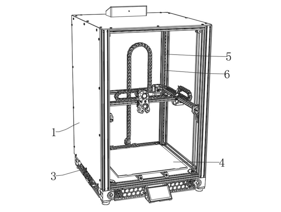
The patent’s answer is a fixed build platform with a moving gantry system.
Instead of raising and lowering the print bed, the proposed machine keeps the platform at the bottom of the enclosure and moves the printhead system in three dimensions. Four lift drive mechanisms are placed at the corners of the machine. These use motors, pulleys, synchronous belts, and linear rails to raise and lower the moving assembly.
In other words, the printed part does not become part of the Z axis load problem. That is a motion system design that’s been used before (e.g. CoreXY), but there’s more here.
As a part grows, it becomes heavier. If the bed is moving upward or downward during the print, the motion system must handle the changing mass of the part and bed together. The patent argues this can contribute to instability, visible Z banding, and layer misalignment.
Here, the moving mass is intended to remain more consistent because the platform and part stay fixed.
The other notable idea is what the patent calls a spatial flexible constraint network. This appears to be a set of flexible rods or supports connecting the moving Z assembly, horizontal carriage, and printhead. The stated purpose is to absorb vibration while maintaining positioning accuracy at the printhead.
That is the interesting part. Many high speed FFF printers rely on stiffness, acceleration tuning, input shaping, and careful belt paths. This design seems to add a deliberate vibration absorbing structure to the motion system, rather than only trying to make everything more rigid.
The patent also includes a compact enclosure. The electrical components are placed in a bottom base section, with ventilation holes and quiet speed controlled fans forming a forced convection cooling path. The outer enclosure is described as using sound insulating panels.
The document claims a 650 x 650 x 1100 mm machine size, office grade low noise operation, 16 to 22 hours for a single orthotic device, more than three times higher X/Y/Z linked motion speed, over 50% overall efficiency improvement, and 7 / 24 hour continuous operation.
Prosthetic and orthotic production is not simply about speed. Parts may require reliable fit, repeatable mechanical behavior, good surface quality, biocompatible material choices, and a workflow that clinicians or technicians can actually operate. A printer targeting that market has to be more than just fast.
Orthotic and prosthetic production is one of the better use cases for large format custom FFF: every part is different, digital scan to print workflows are plausible, and local production can reduce turnaround time.
We will have to wait to see if this concept becomes a real machine, and whether the flexible support concept improves tall part quality without introducing new calibration or maintenance problems.
Via Espacenet