
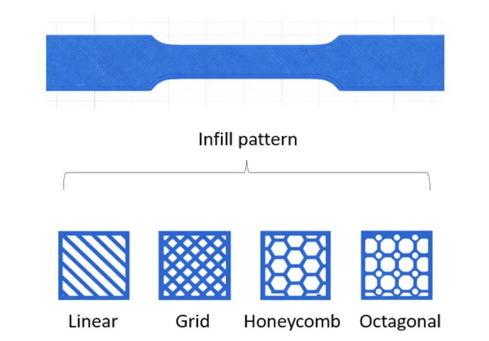
Changing two print settings more than doubled the measured tensile strength of a 3D printed part.
That’s the most incredible result in research led by Farid Bettine and colleagues examining how infill geometry and build orientation affect parts made by Fused Filament Fabrication (FFF). But the study also shows why finding the strongest settings isn’t as straightforward as choosing a winning infill pattern.
The researchers used Zortrax Z-ULTRAT, an ABS/polycarbonate blend, to produce tensile specimens on a Zortrax M300 Plus. They tried four infill patterns — linear, grid, honeycomb and octagonal — at five build orientations: 0, 30, 45, 60 and 90 degrees.
That gave them 20 combinations. Everything else, including 50% infill, a 240C nozzle temperature and 0.15mm layers, stayed fixed. They pulled the specimens apart on a tensile testing machine and recorded stiffness, yield stress, maximum tensile strength and stress at break.
The weakest combination was linear infill at 45 degrees, with tensile strength of just 18.60 MPa. Honeycomb at 90 degrees reached 38.41 MPa — a 106.5% increase, achieved without changing the polymer or infill percentage.
It’s tempting to declare honeycomb the winner and move on. But that doesn’t work.
Grid infill at 60 degrees recorded the highest yield stress, 37.36 MPa, and the highest breaking stress, 34.13 MPa. Honeycomb at 45 degrees, meanwhile, was the stiffest configuration, with an elastic modulus of 2.97 GPa. Its yield stress was only 20.26 MPa.
Stiffness tells you how much a part resists deformation under load. Yield stress tells you when permanent deformation begins. Maximum tensile strength indicates the peak stress it withstands. Depending on the application, these can lead to different preferred print settings.
And the pattern interacts with orientation. Honeycomb at 30 degrees reached only 25.36 MPa tensile strength, actually below the 30.23 MPa recorded by linear infill at the same angle. There isn’t a universally superior pattern even within this small test.
The likely explanation is the way extrusion paths carry force. Some configurations place more material along continuous load paths, while others transfer stress across intersections and layer boundaries. The researchers did not examine fracture surfaces, however, so these mechanisms remain interpretations of the tensile results.
The team then introduced artificial intelligence to sort through the competing goals. Four separately trained neural networks predicted the mechanical properties, while an optimization algorithm searched for configurations that offered worthwhile compromises rather than a single highest score.
The software retained eight of the 20 combinations as possible trade-offs. None used octagonal infill. A designer seeking maximum stiffness could consider honeycomb at 45 degrees; one prioritizing strength might prefer honeycomb at 90 degrees or grid at 60 degrees.
There’s some questions about these result.s The original experimental campaign already covered every combination the optimizer was allowed to select. The model therefore organized known options; it didn’t discover a new print setting.
Its reported correlations were high, around 0.98, but the dataset contained only 20 configuration-level results, with no available replicate records and a very small evaluation set. One neural network even had 180 trainable parameters, considerably more than the number of experimental configurations, so that’s a bit suspicious.
I can imagine this idea becoming useful inside slicing software, where the operator specifies what a part must withstand and the software selects an infill and orientation accordingly. First, though, it would need much more testing across parts, materials and loads.
A recommendation based on one set of tensile specimens is a starting point, not a strength guarantee.