

A plastic weld can fail before the welding equipment is even switched on.
That’s the observation from an academic review of methods for welding thermoplastic parts made by FFF. The researchers examined six different joining approaches, but the most frequently seen issue was the material the printer left behind at the joint.
Why weld printed parts at all? One obvious reason is size. A part that’s too big for the build volume could be divided into printable sections, then joined together later. That sounds easy until you think about what’s inside an FFF part.
Infill is essentially voids inside the print. Those spaces are good for lowering material use, but they can become a big problem when a weld requires softened plastic to flow together and form a continuous connection.
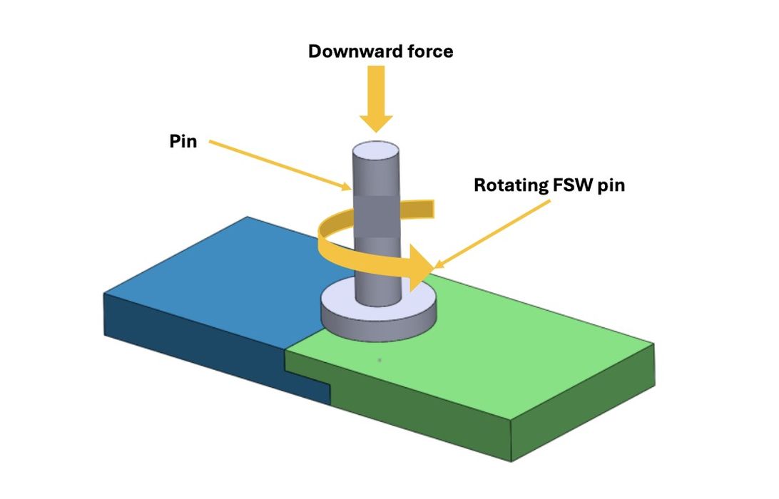
Consider friction stir welding. A rotating pin is pushed into the seam and moved along it. Friction and deformation heat and soften the plastic, while the pin moves material around. The joint forms as the disturbed material consolidates and cools.
But what happens when the pin encounters mostly empty infill?
The study looks at an experiment on PLA Plus in which a configuration using 60% local infill achieved 17.83 MPa tensile strength. A configuration with 20% local infill reached only 3.32 MPa. The settings were specific to those tests, so 60% is certainly not some universal welding recipe.
A part might have lightweight infill for most of its volume, while the planned weld area is printed differently to provide enough material for joining.
Ultrasonic welding uses high-frequency vibrations and pressure to heat the interface between parts. Some of the reviewed experiments included printed “energy directors” — small raised features that concentrate energy where bonding should occur.
The shape of those features changed the results. Cross-shaped energy directors on PLA sometimes produced stronger joints than triangular or semicircular versions. But they also suffered more thermal degradation and excess molten material under certain conditions.
More heating isn’t necessarily better.
Laser joining tells a similar tale. In one study of overlapping white and black PLA parts, shear strength exceeded 10 MPa within a particular range of laser energy. Increasing energy further reduced strength and deformed the material.
And even elaborate joint geometry can backfire. One rotary friction welding study tried interlocking PLA features, which might seem like an obvious way to strengthen the connection. Instead, tensile strength was only about 30% of the control specimens. Excess plastic accumulated in the interlocking region and restricted material flow.
They also cover friction stir spot welding and microwave-assisted welding, where little research has been done.
The conclusion is this: if a large FFF component is going to be welded, the joint’s design should probably influence the CAD model and slicing settings right from the start.
We know how to split a model to fit a printer. Designing the split so the pieces can be reliably welded turns out to be a very different problem.
Via Teknomekanik