
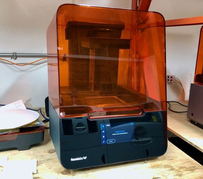
I had the chance to put together a Formlabs Form 3 SLA 3D printer and found the device a great improvement over the Form 2.
This is part two of a two-part series on the Formlabs Form 3 3D printer. Please read part one.
Operating The Form 3 3D Printer
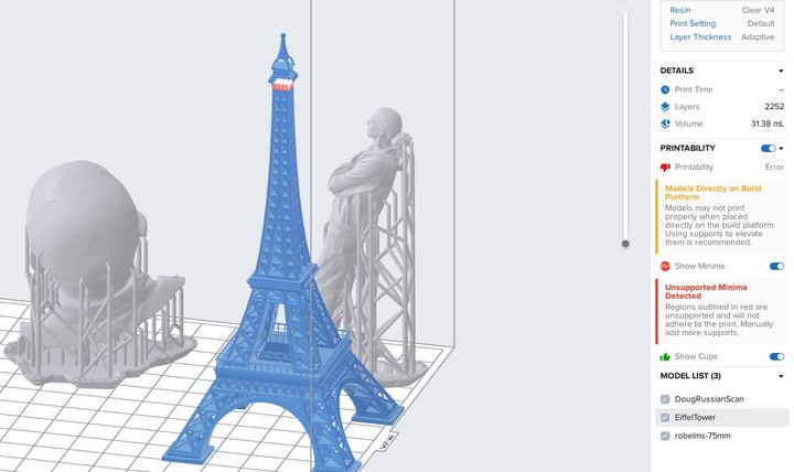
Operation of the Form 3 3D printer is as straightforward as its predecessor, the Form 2. Both use the elegant PreForm software tool, which is certainly the smoothest and easiest-to-use 3D print slicing software I’ve yet seen. It is very straightforward to import a model, pick and orient a material, prepare support structures, and send it off to the 3D printer via the network. In fact, PreForm includes a “one touch” button that does all that for you automatically if you so desire.

Once the print has “arrived” at the 3D printer itself, there is a bit of manual work to commence 3D printing. That’s because in spite of PreForm’s smarts, it really doesn’t know the physical state of the Form 3. You have to manually confirm that the build plate is securely attached and that the vent on top of the resin cartridge is open. Once you do that, printing begins.
The Form 3 uses a redesigned method of 3D printing that Formlabs calls “low force stereolithography, or “LFS”. Basically they’ve adjusted the laser system to provide for a more consistent delivery of energy to the resin, with enhanced tuning, and this results in more accurate and higher-quality 3D prints.
One of the best new features is a new support structure approach that results, more or less, with “breakaway” support structures. From my test prints it seems the increased LFS accuracy allows them to minimize the contact point between the support and the model. This usually means the support can be broken away, and you should be able to 3D print objects with more fragile geometries.
In some 3D prints I found this to be true: I could simply grab the raft & twist, and the entire support structure ripped off. This should be a gamechanger for operations with continuous prints taking place, as the amount of post-processing labor could be significantly reduced.
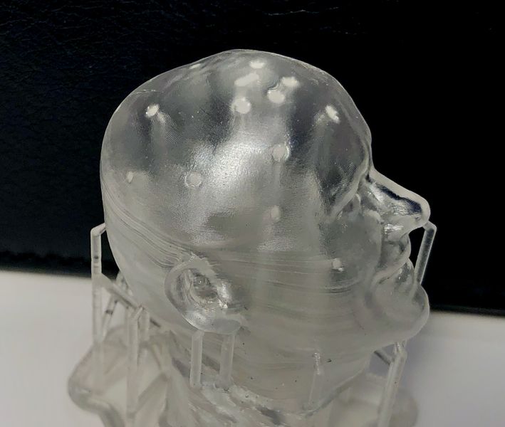
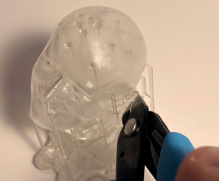
However, in some of my tests this did not happen. In this test of my standard Robert head, you’ll note there were support structures inside the hollow 3D model. These could not easily be ripped out as above, and instead I had to painstakingly remove them with needle nose pliers.
There’s one other effect I noticed with this particular test model, and it had to do with post-processing. I used the Formlabs Wash & Cure stations to clean off stray resin and complete UV curing, and this almost always works quite well. However, on the Robert head it did not.
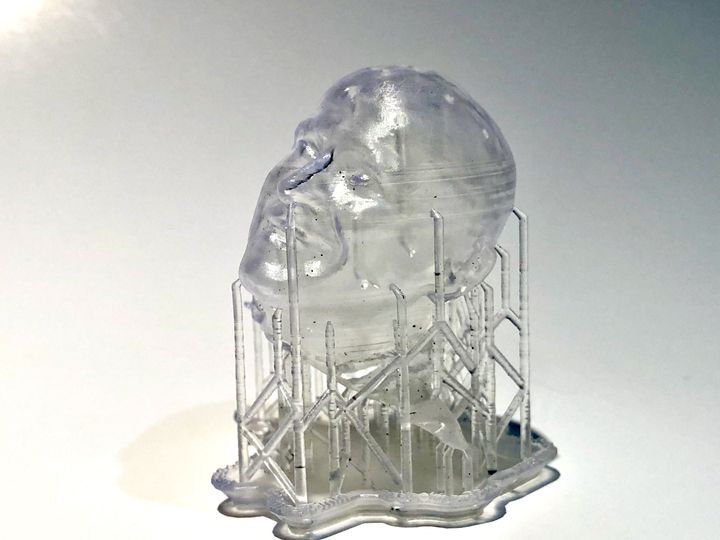
When removing the supports from inside the hollow portion, I found some would shatter. No problem, I thought, just shake the head and the bits will fall out. But they did not. They were stuck inside the head because it was still wet with resin!
Evidently the wash station had problems circulating IPA into the hollow, and the residual resin was not completely cleaned away. Worse, this resin did not cure in the UV station, and remained wet, long afterwards. Eventually I put the model upside down in the sun for an afternoon and that did the trick.
This is certainly not a problem with the Form 3, but rather an operator error on my part. I should have realized this particular geometry would have trouble in the wash station, and thus I should have stepped up the duration significantly. I’ll do better next time!
Form 3D Print Quality
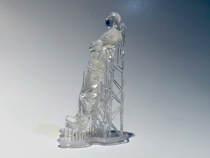
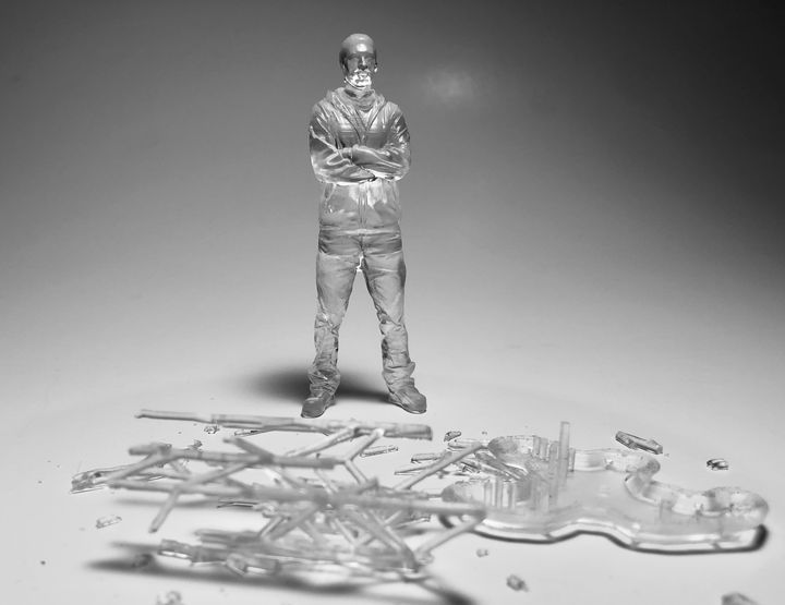
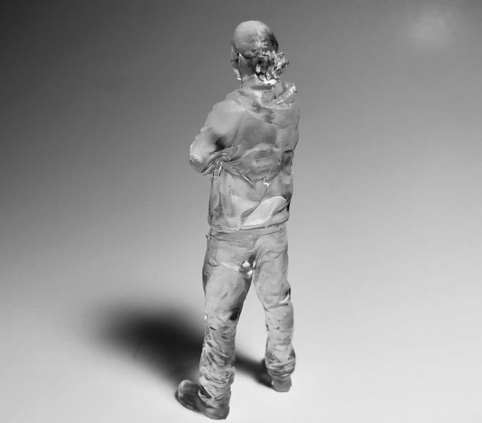
The prints I’ve obtained from the Form 3 were generally outstanding in quality. Here you can see a magnificent 3D print of a body scan I recently obtained:
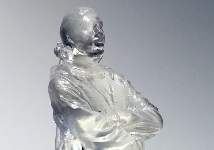
There’s hardly any evidence of layer lines at all on this print unless you’re looking with a magnifying glass. Note that I specifically oriented the 3D print to ensure the support structures were on the rear so that they would not mess up the front of the model. However, I found the support structure contact points were easily rubbed off, leaving a near-perfect surface on all sides of the print.
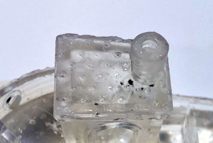
I didn’t fare so well with a test #3DBenchy. I printed it upside down to ensure a good hull surface. While the hull had excellent smoothness, the top part of the tiny ship suffered when I removed the support structures. I’m not quite sure why this occurred, but perhaps I should try this model once again.
Another interesting print features is “Adaptive Layers”. The idea here is that instead of repeatedly printing fine layers on surfaces that do not have a lot of differentiating detail, print with larger layers to speed up the print. In theory this should not affect the quality of the output.
To test this I printed two versions of Cosmo Wenman’s amazing Venus De Milo 3D model, one with adaptive layers and one without. Note these were quite tiny prints, only 50mm tall, and less than 10mm wide.
Here you can see the difference on the two prints:
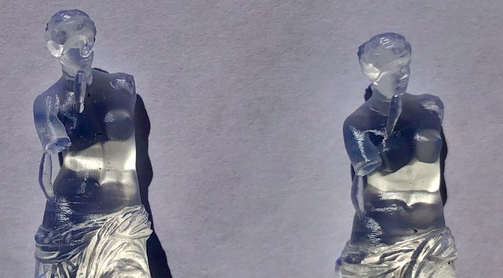
It appeared to my eyes that the non-adaptive version, which printed at the finest resolution possible with this clear material, came out very slightly better. But really, this is for all intents invisible.
I suspect, however, that the feature is best used for larger prints of mechanical objects where speed advantages are far more apparent.
As I expected, the Form 3 is an improvement over the Form 2 in several important ways, and it certainly should be considered for any serious resin 3D printing application.
This is part two of a two-part series on the Formlabs Form 3 3D printer. Please read part one.
Via Formlabs
Just sharing for all your readers (I’m sure you have solved your problem and moved on).
Looks like your benchy was positioned with the damaged surface parallel to the bed (flat), and this surface was near the raft. Not a good orientation because of the following two things…
-First, with resin 3d printing, avoid flat faces parallel to the bed, imagine a sheet of plastic wrap… now imagine picking up the sheet with your finder tips…by the way, it is glued to the table and you need to peel it off… now, how easy is it to keep everything flat. The first layers of the flat surface are likely to ripple, tear, and sag.
-Second, the surface was likely positioned tight to to the raft and the coating resin had no where to drain away. Some resin may have even have climbed the supports through capillary action. This pooled a lot of coating resin in the area. This pooled resin my have received stray light or maybe didn’t rinse well.
So 2 things…
Start your part on a corner, with a small surface area (point if possible) down, and watch for flat faces – especially highly visible – get these important faces angled. (Try for a point start, grow slowly getting fatter, and taper back to a small surface to end.) Also, remember faces at 5 to 20 (or so) degrees to the build plate can also show layering easier. Get those flat and slightly curved faces tilted to 30 degrees or more.
Also, don’t trap resin against the raft (also, solved by the previous orientation advise). And wash the part very well if you have a thick forest of supports that tend to trap coating resin.
Note: Kerry, Preform defaults too conservative on the support point diameter, try some prints with the setting moved just to the right of the warning (go to a warning state and then backup one click) probably .3mm for your resin.
Thanks for the tips! We try to use default settings for review testing, as that should demonstrate the basic capabilities of the device. We’ll try using these methods next time we’re on that machine.