
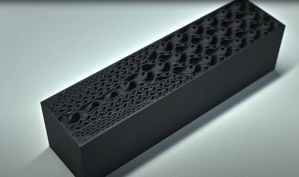
There’s a new — and free — tool to automatically generate variable infill for FFF 3D print jobs.
The tool is called Strecs, and it’s developed by Taniguchi Tomohiro, who wanted a better way to generate complex infill patterns. He explains:
“As an engineering enthusiast, I wanted to apply scientific principles to 3D printing. My goal was to create parts with an optimal strength-to-weight ratio, not just uniform infill.”
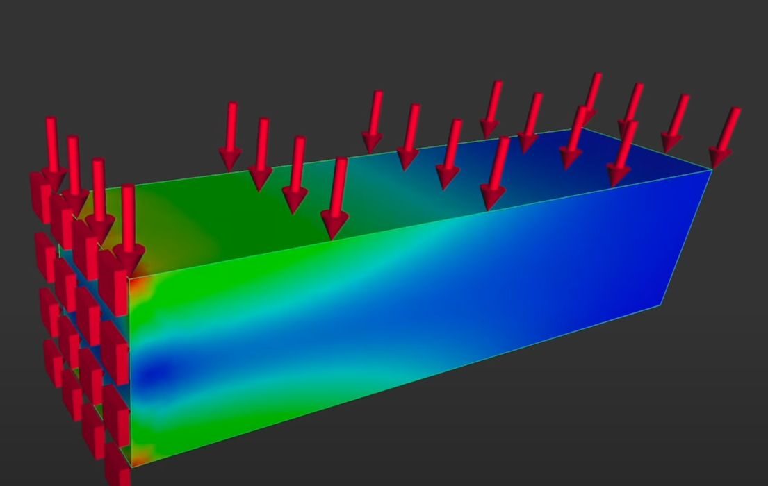
What exactly does it do? The concept is to perform a mechanical stress analysis on a part, and then generate an infill pattern to match the stress levels. Areas of higher stress get more dense infill, and vice versa. This allows you to print strong parts with less material.
This sounds like an advanced technique that might be used by professionals, and it is — it’s just that here we have a free tool that allows you to do something very similar.
The usage process involves a couple of different tools. Here’s the basic workflow, after installing Strecs from their GitHub page:
- Create a part 3D model in your tool of choice, as long as you can export it in STL format.
- Import the part into FreeCAD, an open source 3D modeling tool.
- Inside FreeCAD, use its own FEA tool to prepare a stress analysis of the part.
- Export that analysis as a VTU file.
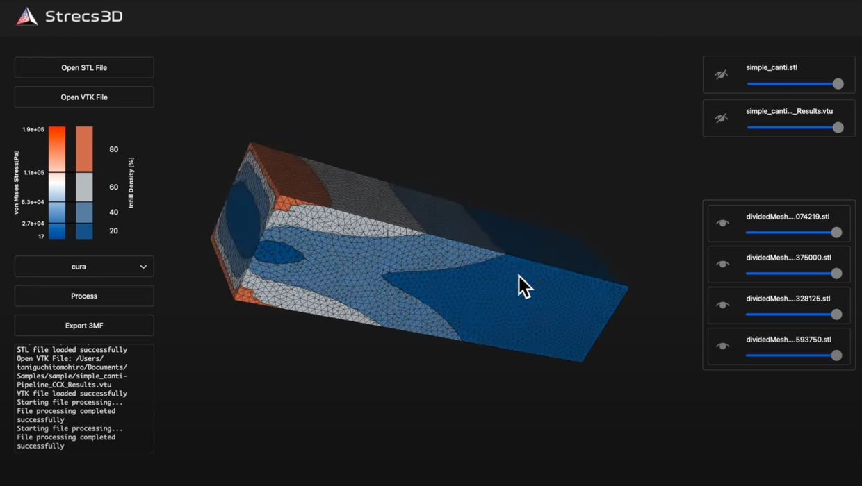
- Import both the STL and VTU files into Strecs.
- Strecs divides the part into four areas each having unique infill density.
- Adjust the sliders in Strecs to match the situation.
- Export the resulting 3MF file.
- Slice and print the 3MF file using your normal 3D printing workflow.
At the top you can see the results of this workflow, where Tomohiro analyzed stress on a box in a simple scenario. The system can handle more complex scenarios, of course. He has also provided a walkthrough video showing how this all works:
You will also need to install FreeCAD, if you haven’t already. I’ve used FreeCAD previously, but I was not aware that it included an FEA feature. It seems a bit hidden, but Tomohiro shows where to find it in the video.
This is a very interesting workflow that might provide some benefit to 3D printer operators, especially since it is entirely free — both Strecs and FreeCAD are available at no charge.
Does it work? Well, it certainly does generate varying densities of infill. But do these actually provide the strength required? It seems there might be more to the story, according to Reddit contributor and strength engineer Imposter_Engineer, who listed some issues that would affect the performance of Strecs:
Printed parts behave very differently from the model. In your example, you’re using a fully solid, presumably isotropic beam in the FEA. Layer bonding is weaker than in-plane strength, and the infill pattern introduces orthotropic behaviour. The real load paths and stress distribution are dominated by anisotropy and voids, not by the uniform bulk material assumption in your FEA.
von Mises is a scalar yield criterion for ductile, isotropic materials in multiaxial loading. It’s not a measure of “how much infill you need.” For anisotropic plastics, layer-by-layer builds, and brittle failure modes, it’s the wrong metric entirely.
The internal geometry affects stiffness, which in turn changes stress distribution. If you change infill density based on stress, you’ve changed the stiffness, which changes the stress, which changes the “optimal” infill. Without iterating the simulation with the actual printed geometry, you’re just tuning to the wrong structure.”
As a result, Imposter_Engineer believes that Strecs “needs a lot more work to even be directionally practical.”
Nevertheless, it could be useful as an introduction to the FEA process for some 3D printer operators.