
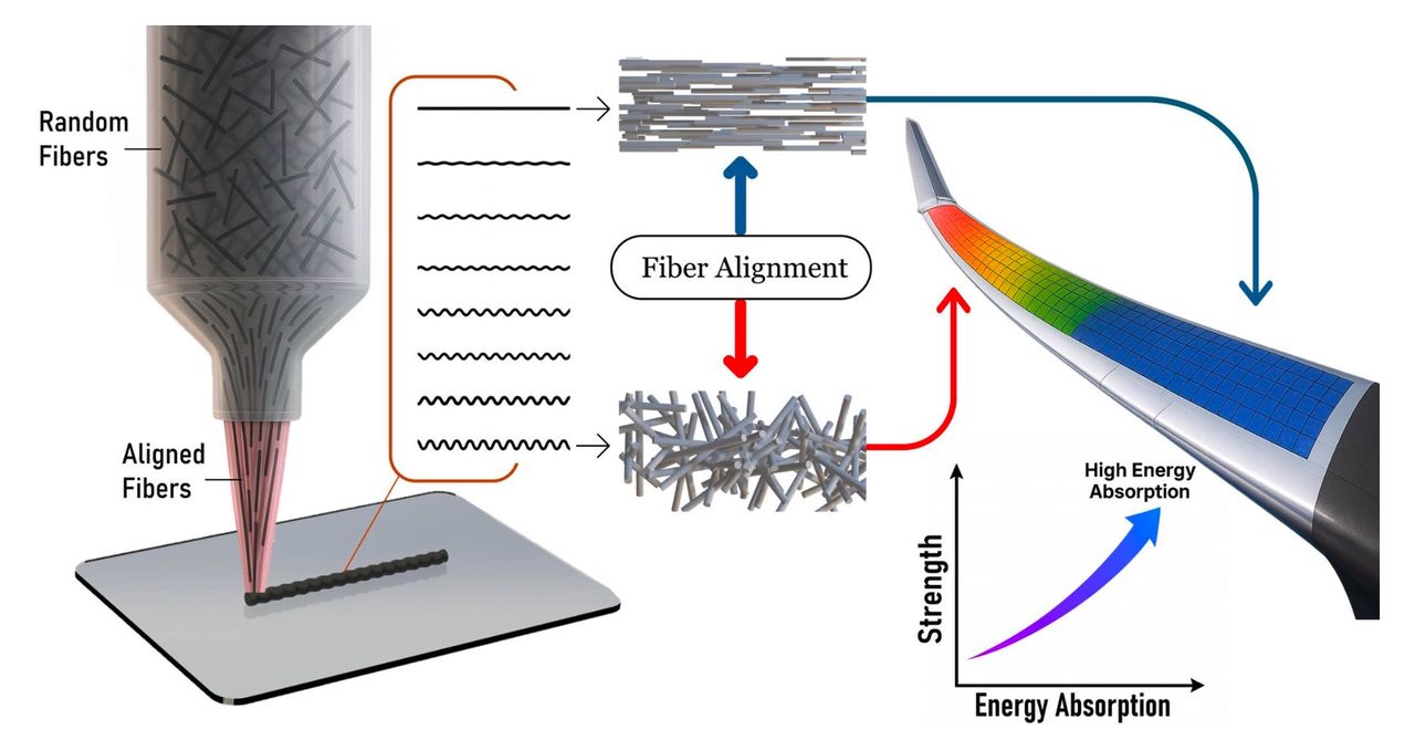
Researchers have found a way to increase energy absorption in 3D printed carbon fiber composites simply by changing how the print head moves.
Researchers Kaan Nuhoglu and Emrah Celik of the University of Miami, along with Vikas Varshney of the US Air Force Research Laboratory, investigated functionally graded carbon fiber reinforced thermoset composites produced using direct ink writing. Their objective was to control stiffness within a part without changing its overall geometry or material composition.
This is particularly interesting for aerospace applications, where structures frequently require apparently contradictory properties. A wing component, for example, might need high stiffness in one region while permitting considerable deformation elsewhere.
Traditionally, engineers handle this by adding ribs, stiffeners, joints or other structural features. Those additions can increase weight and manufacturing complexity.
Programming The Fibers
The researchers instead manipulated the orientation of chopped carbon fibers already present in the material.
In DIW composite printing, material passing through the nozzle experiences shear forces that tend to align fibers with the extrusion direction. This usually creates strongly anisotropic parts, with substantially different mechanical properties depending on direction.
The researchers discovered they could disrupt that alignment by making the nozzle follow a sinusoidal, oscillating toolpath rather than a straight line. Increasing the oscillation amplitude progressively changed the fiber orientation, eventually producing a largely randomized fiber arrangement.
Interestingly, pushing the oscillation even further began aligning fibers in a new transverse direction. This means the technique can potentially select among aligned, randomized and redirected fiber structures merely through G code.
Thirteen different oscillation conditions were tested, using a constant spatial frequency while varying lateral amplitude from 0.125 to 2.000mm. Microscopy and image analysis were then used to quantify the resulting fiber alignment.
That opens up an unusual possibility: changing mechanical properties continuously across a single printed object without switching materials.
Printing A Mechanical Gradient
The team used finite element analysis to determine where different fiber orientations should appear in a beam undergoing bending.
Their optimized design placed strongly aligned fibers in high stress regions, while more randomized fibers were positioned where additional deformation and energy dissipation were desirable.
They then printed 120 x 13 x 3 mm test specimens using an epoxy based ink containing 4.9% chopped carbon fiber by volume and 3.6% nanoclay. The custom DIW system was based on a Creality Ender 5 motion platform fitted with pressure driven extrusion hardware.
Three point bending tests showed the optimized configuration absorbed nearly 10% more energy than the fully aligned reference while retaining comparable peak flexural strength.
That may not sound like an enormous increase, but there is an important detail: nothing was added to the part. The material, fiber loading, nozzle and external geometry remained unchanged. Only the toolpath changed.
The researchers also point out that the relatively low carbon fiber concentration limits the difference between aligned and randomized regions. Higher fiber loadings could potentially produce larger mechanical differences.
There are some practical issues ahead. Rapid oscillatory motion introduces acceleration limits, extrusion continuity problems and small deviations from the intended fiber orientations. Their simulations consequently predicted somewhat better performance than the physical specimens achieved.
Nevertheless, this is an intriguing demonstration of how toolpaths themselves can become a materials engineering parameter.
We normally think of slicing software as deciding where material goes. Techniques like this suggest future slicers might also decide what the material should become after it gets there.
Via Springer