
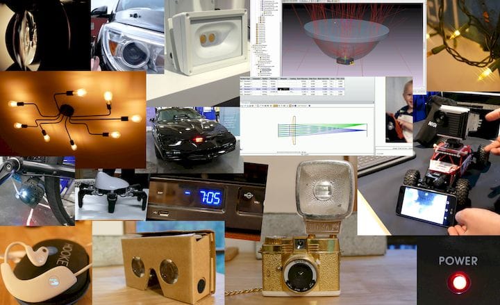
![Optical engineering software [Source: SolidSmack]](https://fabbaloo.com/wp-content/uploads/2020/05/image-asset_img_5eb096451d80c.jpg)
If you’re engineering hardware that has any one of: a camera, an LED, a display, an IR sensor, a lens, a laser, a reflector, or an optical fiber, guess what?!
You’re working with an optical system. What’s more, there’s an entire branch of engineering that specializes in optics. And, if you’re not involving an optical engineer in your development, you’re very likely doing it wrong. And time-consuming-ly. And expensively. And possibly dangerously.
Lots of Big, Costly, Preventable Mistakes
Most of y’all working in startups (and sometimes even larger corporations) are doing it wrong. I know because I am an optical engineer (OE) running an engineering consultancy (SpireStarter.com). Last year, I traveled almost 100% of the time in the US and abroad meeting hardware engineers who needed help with optical engineering. A whopping 85% of the work I did last year was done for free. Why? Because so many of those hardware companies 1) needed to learn what optical engineering was and 2) how it could benefit their specific situations.
Also, most of the engineers I talked to thought an optical engineer was the person who designed their glasses. Breaking News: that is not what we do.
3 Out of 3 Optical Pros Agree
I didn’t want you to just take my word on all this. That’s why I asked engineers at two of the largest optical simulation software providers to chime in. Special thanks for the contributions from Patrick Le Houillier (and Jake Jacobsen, Ph.D narrating in the video) of Synopsys and Bob Householder of Zemax!
Video: Optical Simulation Software in Action
Below is the video that includes an inside look at how the software from Synopsys and Zemax work (LightTools at 7:20 and Zemax OpticStudio at 11:40, respectively).
Specialties within Optical Engineering
There are a ton of different tracks in optical engineering. Most optical engineers (OEs) will only have experience in a couple. I have experience in an abnormally large number of specialties, but definitely not all. This is why I collaborate with different mixes of specialists depending on the project.
You’ll hear OEs say, “in the end, light is light.” Which means: light follows the same rules of physics no matter the applications. That’s true, but different specialties and even different applications within a specialty can be totally different ballgames in terms of engineering requirements and tools.
The most common two boxes to divide optical engineering specialties into are imaging and non-imaging.
Imaging Optics
![Examples of devices with imaging optics: Google Cardboard and an old-timey camera. [Source: SolidSmack]](https://fabbaloo.com/wp-content/uploads/2020/05/optical-engineering-optical-examples_img_5eb096458eab0.jpg)
Imaging optics include all optical devices where you’re creating an image. The image could be a picture, a video, or some other representation of real-life that falls on your eyeball. Examples are things like:
-
Cameras (including those in machine vision systems)
-
Microscopes
-
Telescopes and Binoculars
-
Projectors
-
VR Goggles
That scope your proctologist jams up your innards? Yeah, you can thank an optical engineer for that, too.
Non-Imaging Optics
![Examples of devices with non-imaging optics: 2013 Buick Enclave headlamp (which may be a project I personally was engineer on and had multiple migraines over) and LED-powered indicator light on Hooke Verse headphones. [Source: SolidSmack]](https://fabbaloo.com/wp-content/uploads/2020/05/image-asset_img_5eb09645d97ac.jpg)
The term “non-imaging optics” lazily contains all the other types of optical things that aren’t imaging. It includes a LOT of specialties, such as:
-
Illumination (aka Lighting)
-
Lasers
-
LiDAR
-
Fiber Optics
-
Optical Sensors (e.g. IR sensors, light curtains, visible light sensors)
-
Spectroscopy
Pretty much anything else using an LED…
Tools of Optical Engineering
As I mentioned, the tools an OE might use can vary widely depending on application. These include what engineers use to design, simulate, or “debug” in virtual environments, and test in real life.
Optical Simulation Software
Not too long ago, a lot of optical engineering design and analysis was done by hand. Now, we have super fast computers and mind-blowing simulation programs. They can show us just how a design will perform before a tool is ever cut. Work that might have been done with 50 mathematical calculations and pencil drawings on human-sized physical prints is now replaced by millions of calculations on a PC and realistic renderings.
What are Ray Traces?
Most of that simulation work (but not all) is done with ray traces. In a typical simulation, you’ll have a video-game version of all the components of your optical system. So you might have, say, an LED, a lens, some housing geometry, and some sort of detector.
![Setting up a simulation in LightTools: here, in the Land of Make Believe, we have a virtual lens sitting on top of a pretend LED. [Source: SolidSmack]](https://fabbaloo.com/wp-content/uploads/2020/05/optical-engineering-setting-up-simulation_img_5eb096464caee.jpg)
In the simulation, you’ll model a virtual version of each of these. For your LED, maybe you create a source model of the same colors and light distribution and overall amount of light of the diode. Let’s say the lens you want to create is pretty simple and you create that piece right in the simulation software. Maybe the housing is some CAD a mechanical engineer created in SolidWorks. So, you get a .STP file (or whatever format you can use) from the ME and import it into the simulation. Next, you set up a detector in the area where you want light to go so you can see if you succeeded.
Then comes the most difficult part: setting material and texture attributes for all the physical parts. These models should be based on your past experience comparing real life to simulation. (Little changes here can COMPLETELY change your result!)
Last, you might tell that pretend LED you created to turn itself into 1 million light rays based on its model, and you hit “GO”.
Read the rest at SolidSmack


VSHAPER has released a pair of interesting 3D printing guides, and unlike most beginner guides, these are designed for engineers.