
As virtual simulation advances, innovation gets faster and becomes less costly.
Simulation technology is continually advancing to model increasingly real-world product behavior; however, many companies lag in its adoption.
A recent survey found that only 37 percent of respondents said they applied manufacturing simulation during the product design phase. The vast majority were checking product manufacturability only once the design was completed. Sometimes simulation was used even later after a product failure occurred. Lack of adoption of simulation-driven design for manufacturing (SDfM) is often due to a company’s cost concerns and lack of training and resources, despite managers being cognizant of its advantages.
However, by eschewing SDfM, companies are missing out on the ability to reduce product manufacturing costs, streamline the design process, ramp up production schedules and more efficiently deliver products to customers. These advantages that SDfM provides come amid increasing product complexity and consumer demand for faster time-to-market intervals.
“The manufacturability of a product can greatly affect the cost,” said Altair Vice President of Marketing Simone Bonino, who spoke alongside other presenters at the Future.Industry 2021 event in October. “If you are simulating early and often, you are really accelerating design. That’s when you see the value of a simulation-driven design for manufacturability approach. It enables generative design for all manufacturing processes with ease. It allows you to analyze complex assemblies with great accuracy. And it optimizes the design for manufacturability by selecting the best process early.”
Bonino said that Altair began introducing the simulation-driven design concept nearly two decades ago. Today, SDfM solutions cover a broad range of processes like 3D printing, casting, metal forming, injection molding, extrusion, process manufacturing, polyurethane forming, circuit boards and electronics, and composites—each with a different software product to enable the specialized simulation, such as the recently launched Inspire Mold for injection molding and Inspire PolyFoam for polyurethane forming.
Additionally, engineers can utilize the Altair Material Data Center to search or browse for materials, visualize material properties, compare material types, and get help with choosing the relevant simulation software and export simulation data files.
By starting very early in the development cycle, an array of products is well-suited to simulation. In addition, using SDfM as a first step in the process results in better performance and manufacturability because team collaboration, evaluation and rapid convergence are still possible, Bonino said. The technology also enables the evaluation of single and coupled physics performance, can be used to generate original designs for innovative products, and yields greater insights into the overall manufacturing process.
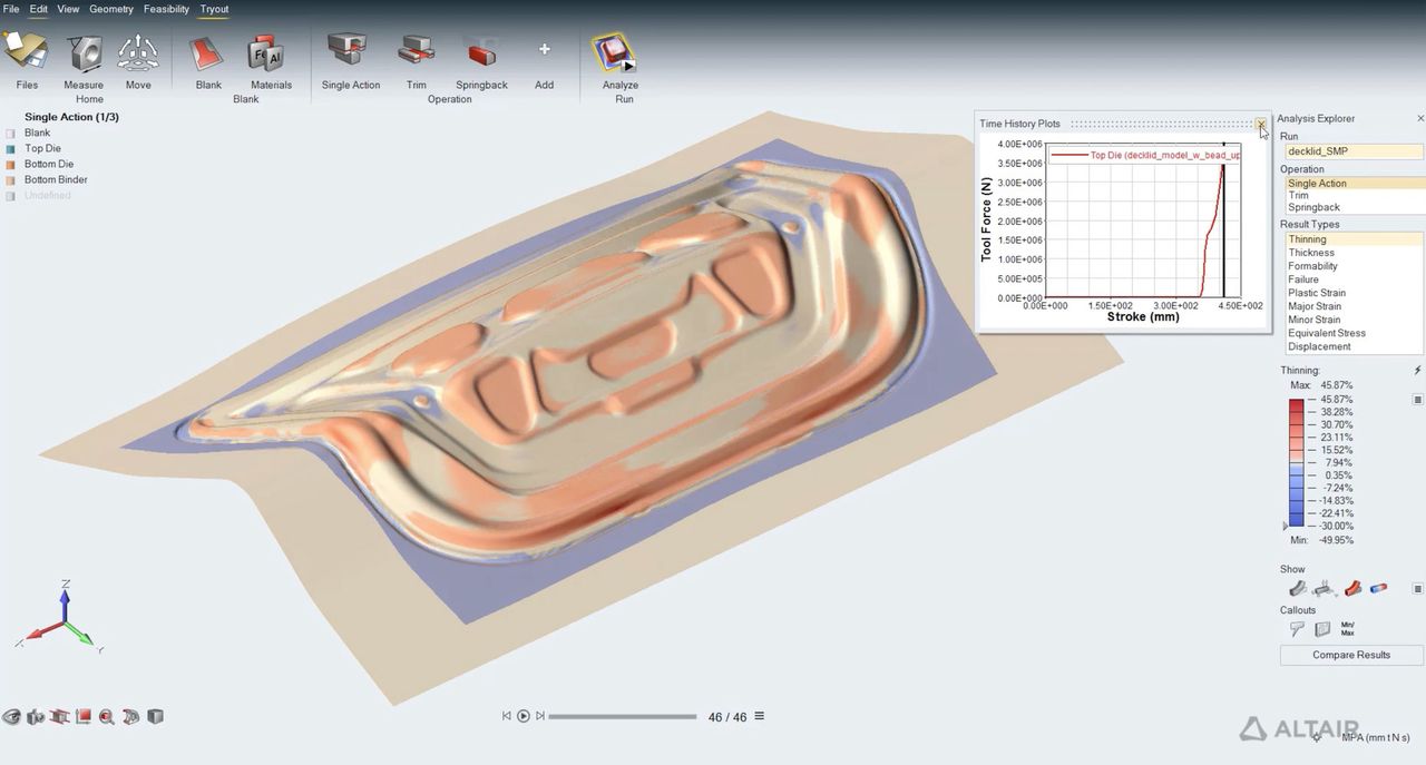
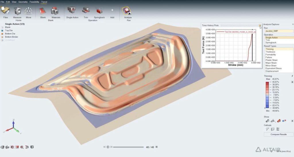
To illustrate the potential of SDfM, Altair Application Engineer Chen Meng spoke about predicting manufacturing feasibility for sheet metal parts using virtual methods. She began with an example of a metal battery holder part. The goal was to optimize the holder to maintain performance requirements even under extreme scenarios such as 3.6 Gs of load applied to the part in a hard braking scenario. In addition, other constraints were set for conditions to maximize stiffness and optimization, such as applying no more than 50 MPa of stress and having the first bending mode be greater than 85 Hz.
Instead of conducting a physical trial and error process to manufacture a battery holder that meets the stated goals, Meng advocated performing a systemic simulation to check the manufacturing feasibility during the design process to create a high-performing and manufacturable product while saving time and costs in the development cycle.
The sheet metal manufacturing process entails forming phases where a flat metal sheet is transformed into the final product in multiple steps. Generally, the process begins with a baseline sketch of the design, optimization of the design, design interpretation, manufacturing feasibility analysis and rapid validation—all hopefully resulting in high-performing and manufacturable products.
How the materials behave during the forming process will determine if the part is manufacturable. The behavior is revealed through stress data based on the mechanical properties of materials measured in tensile tests. For example, when a machine stretches a sheet, the deformation is initially elastic and reversible; however, the change could become irreversible if the sheet is extended further. Finally, extreme stretching can cause the sheet to break.
Material tests can determine the deformation limit that leads to the three most common manufacturing defects during sheet metal forming: splits, springback and surface defects. Splits occur when the material is pushed beyond its limits and becomes strained or broken. At the same time, springback defects are mainly caused by imperfections in the behavior of the elastic qualities of the material. Finally, surface defects include slight concave or convex marks. Surface defects are especially relevant for external parts like car doors and are caused by several issues such as too much pressure applied to the part or poor application of tools during the process.
The traditional design process relies on trial and error and corrects the defects with tools and design changes until the product is manufacturable. However, the redesign and rebuilding of tools are time-intensive and expensive processes. Conversely, using virtual simulations to predict the outcome of the formation phases can streamline the process.
According to Meng, there are two main methods for virtual simulation in metal sheet forming: the one-step method and the incremental method. The one-step method, also known as the inverse method, is usually implemented during the early product design phase. It works inversely to the physical process as it begins with the final part shape and then virtually flattens the part to its initial sheet shape.
Read more at ENGINEERING.com