
The 18-month collaboration seeks to develop and test Incus’ LMM 3D printing capabilities for spare parts manufacturing on lunar bases.
Did you know that the famous moon landing performed by the Apollo 11 crew almost ended in disaster? Thanks to Buzz Aldrin’s quick reaction, the two astronauts were able to bypass a broken circuit breaker with a pen and ignite the module’s engine—their only hope to return home safely.
What if in the near future, instead of using a pen to connect the critical circuit, astronauts could have another option? That the scrap metals laying on the moon’s surface could be repurposed into useful parts to repair their spacecraft?
Recently, Austrian engineering firm and OEM start-up Incus began a partnership with the European Space Agency to research how 3D printing technologies can be implemented on lunar bases in order to produce spare parts. Lithoz, a ceramic 3D printing company, and OHB system (subsidiary of OHB SE, a German space technology group) will also be joining this 18-month project.
The goal of the project is to explore and verify the microgravitational capabilities of Incus’ Lithography-based Metal Manufacturing (LMM) technology and its potential applications for spare parts manufacturing and the recycling of lunar base materials.
LMM 101
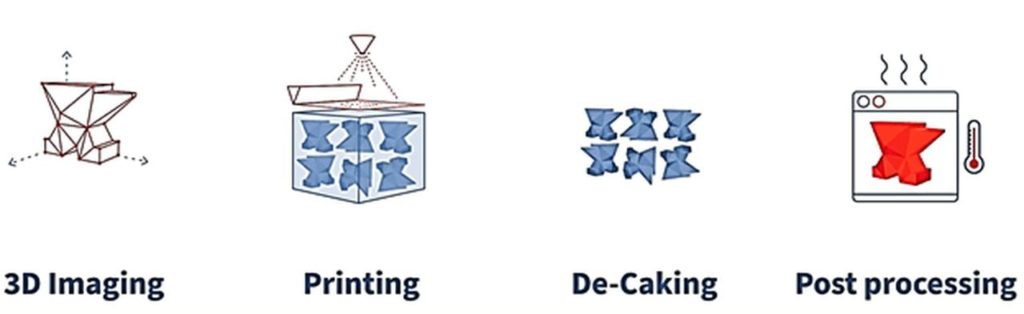
Incus’ LMM process can be divided into four steps:
3D imaging
In order to run 3D printers, CAD models need to be sliced into hundreds or thousands of layers, like a lasagna dish. The slicing software is commonly known as a slicer, and the code that drives the printer is called g-code.
Printing
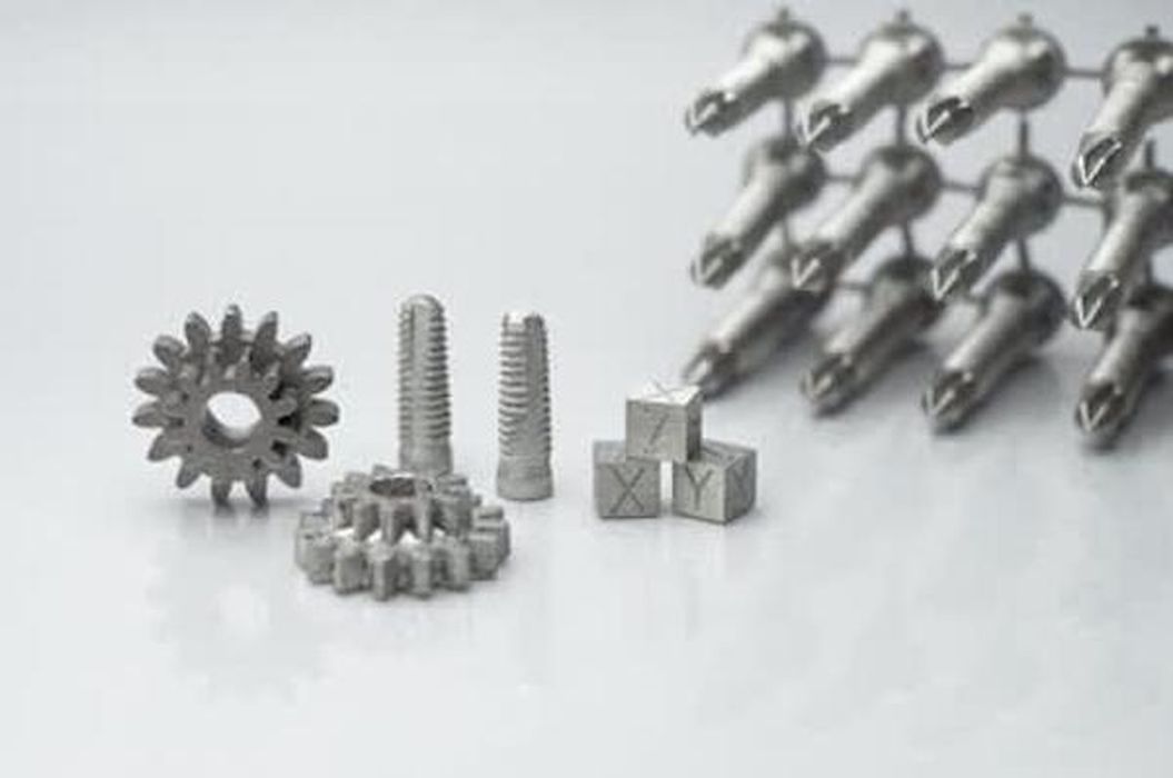
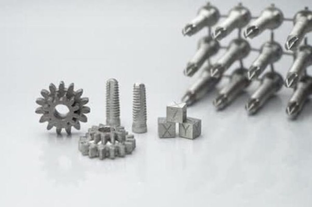
Incus’ flagship LMM printer, Hammer Lab35, utilizes a photopolymerization technique to solidify the resin-metal building material. This material is a mixture of photosensitive resin and metal powders (e.g. 316L steel, titanium, tungsten).
Before each layer of printing, a feedstock extruder evenly distributes a thin layer of the mixture onto the building platform. The layer height can be adjusted between 0.01 to 0.1 mm based on the desired precision.
Next, the printer solidifies a certain region of the mixture layer according to the g-code. This is done through a powerful blue light beam that is emitted by the printer’s 2560 x 1600 emitter screen. A typical wavelength value is 405 to 450 nm. Instead of an LCD emitter, the light beam is emitted by a digital light projector (DLP) or laser source, as more power is required for penetrating the metal powder within the mixture.
By featuring a fully controllable print climate, the printer can reach a lateral precision of 0.035 mm. On top of that, the maximum building volume is 89.6 x 56 x 120 mm, and the maximum printing speed is 100 cubic centimeters or 250 slices per hour.
De-Caking
De-caking is the process of extracting excess building mixture from desired parts with heat. This process typically takes 15 minutes.
Post-Processing
During post-processing, the metal parts will go through a series of treatments, including debinding, sintering and cooling.
Debinding is a critical process to maintain the structural integrity of metal prints. A specialty fluid is used to remove as much binder as possible.
Next, the print is heated to a temperature where it almost melts, using gravity to remove all the small gaps and air bubbles from the print.
Read more at ENGINEERING.com