
An Inventor tutorial.
Like most 3D mechanical modelers, Inventor supports different workflows for designing 3D models.
The traditional (and most common) is bottom-up. In this approach, you build parts and add them to assemblies. You continue working from the bottom level up to the top (hence the name). Because of the relationships between the components, changes to the parts can impact the levels above them.
Bottom-up is best suited when you know many of the details. Things like using purchased (off-the-shelf) parts or existing components, or basing a part off existing designs. You may know what works best with your manufacturing processes. Or you may have a clear picture of what your design will do and look like. Also, this approach is better for collaboration, as people can work on different components at the same time.
Top-down is the opposite of bottom-up. In this approach, you start by defining the result. The result is the main structure or shape of the design. This root then becomes the base for building the parts and assemblies. As you make changes to the base, the changes propagate through all the part’s components. Top-down works well when defining the structure is important and the details can be added later.
What is sometimes called middle-out is an approach in which you can mix methods. There is no one perfect method for all given scenarios. The good news is that Inventor supports many methods of modeling.
Model Layout
One of Inventor’s top-down methods is what Autodesk calls the Model Layout. With Model Layout, you start with a part where you create key parameters and build the assembly layout. You can design this layout in 2D, 3D, or a combination of both.
To use the layout as the assembly structure, build it using sketches. You then add the layout to an assembly (as a reference) and use it to position the components. Instead of constraining components to each other, you constrain them to the layout. Changes to the layout adjust the positions of the components.
Another use of model layouts is to derive the layout into parts and assemblies. The layout becomes the base for the new components, keeping associativity. Therefore, changes made to the layout update the associated models.
Your layout does not need to define the entire assembly. You can use it to design key components, the assembly framework, or its structure. You can also use the layout to position other components, even those built using the bottom-up approach. You can also consider using multiple layouts for the various sections of your design.
Getting Started
It starts with a part and at least one 2D sketch. Then you sketch the design footprint, as in the structure.
Pro tip: When working in an assembly, use Make Layout to automate the process. This creates a new part in the assembly (grounded at the origin) and edits it in place, so you are ready to jump in and start sketching.
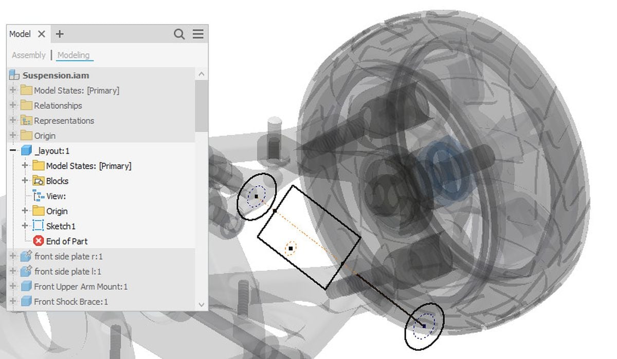
Here, I have designed the shock in 2D to ensure that it will work. I have mixed design approaches and started by adding existing parts to the assembly. I then projected fixed locations of the frame to act as the anchoring geometry. The project (as per my current settings) creates a cross-part association.
Once I had created the needed layout geometry, I added assembly relationships between it and the existing assembly components. You can add relationships between components and sketch objects. If you adjust the layout, the components adjust as well. In addition, changes to the frame update the associated projected geometry in the layout.
Because I did this in 2D, the shock was quick and allowed me to test the kinematics. With this design, I wanted to know if the shock behaved as expected as I rotated and moved the upper and lower control arms. I was also able to flip the script and adjust the 2D shock geometry to measure its effects on the assembly.
Next, I added the components and built relationships with the layout. Inventor does not care if the components are 2D or 3D. In my scenario, I decided to use an existing strut. As I constrained this strut model to the layout, changes to the layout affect the positioning of the strut.
The amount of layout detail (and your effort) will depend on what you need. Is the layout just for verifying the design or do you plan to use the it for building parts?
Making Parts
Use Make Part to create a single part file from your layout. The difference with this feature compared to Derive Part is that it pushes. Make Part derives from the active file instead of into the existing file.
Start by selecting the objects you want to include in the new part. This can be sketch blocks, surface bodies or solids. Clicking OK will create the new part.
Pro tip: You can preselect objects before starting the command. This can be quicker (and easier) in many situations, especially when you know exactly what you want to derive.
As Make Part is based on Derive, you have similar options. This includes setting the Derive style, breaking the link with the base component and setting a Scale factor. You can include other objects like work geometry and parameters in the new part.
Set the new part’s name, file location, and BOM structure, and then select the template to start with.
You can optionally use Place part in target assembly to insert the new component into a new target assembly.
Because I selected a sketch block for the basis of my new part, I used it to build the initial shape. I then added features to complete its form.
Both the shape and position are derived and remain associated. As you change the layout’s block instances, the part file reflects the changes.
With Make Part, the position of a block instance in the target part is identical to its position in the source part relative to the part origin. This is a different behavior than Make Components, which we will look at next.
Although you can use Make Part multiple times to build components from a single layout, it is better to use Make Components to create multiple components from your layout.
Sketch Blocks
What are sketch blocks? They are a way of grouping sketch objects together. The grouped objects then behave as a single element. Inventor provides a way to reuse common shapes and a method of tackling designs.
Use sketch blocks in your layout to represent the components. Because blocks are reusable, you can add instances throughout the layout. Changes to the block definition propagate to all instances. You not only design the assembly layout but also the components themselves.
Want to see more about sketch blocks? Check out my post on sketch blocks here.
Because you are using sketched objects, it can be quicker and easier to design and simulate before committing to 3D modeling. Typically, you only put in enough detail to represent the base shape of a component. Once it is derived into its own file, you can flesh out the details.
Read the rest of this story at ENGINEERING.com