
A new research study looks at a common problem in desktop FFF 3D printing: ringing.
That’s the ripple pattern you see near corners and sharp edges when a printer is moving too fast, or accelerating too hard.
Anyone who has pushed a belt-driven desktop machine knows this tradeoff. Higher speed looks good on a spec sheet, but once the frame, belts, motors, carriage, or toolhead begin to resonate, the print surface tells the truth.
The usual answer is input shaping.
This is now common in Klipper firmware, increasingly available in Marlin, and built into some commercial printer systems. The idea is to measure the printer’s vibration behavior and then adjust motion commands so the machine does not shake itself into producing visible artifacts.
That works.
But there’s one issue: it often requires an accelerometer, printer-specific calibration, and occasional retuning after mechanical changes. Many users skip the proper process and rely on generic presets. That is better than nothing, but it is definitely not the same as actually knowing how a specific machine behaves.
The new paper, formally titled “A Verifiable Steady-State Frequency–Velocity Mapping for Desktop FDM Printers Based on an Electromechanical Coupling Framework,” proposes a more direct way to look at the problem.
In other words: instead of only asking, “What frequency does this printer resonate at?”, the authors ask, “What print speed is exciting that frequency?”
That is an interesting and different way of looking at the problem.
The basic idea is pretty straightforward. Stepper motors do not move in a continuous, perfectly smooth way. They move in steps, and those steps occur at a rate determined by commanded velocity, microstepping, pulley size, belt pitch, and the printer’s steps-per-millimeter setting.
That step rate is a frequency.
So when you command a toolhead to move at a given speed, you are also generating a particular excitation frequency in the machine. Change the speed, and you change the frequency. Sweep through a range of speeds, and you sweep through a range of frequencies.
Eventually, you may hit a structural mode. That is when the printer starts ringing.
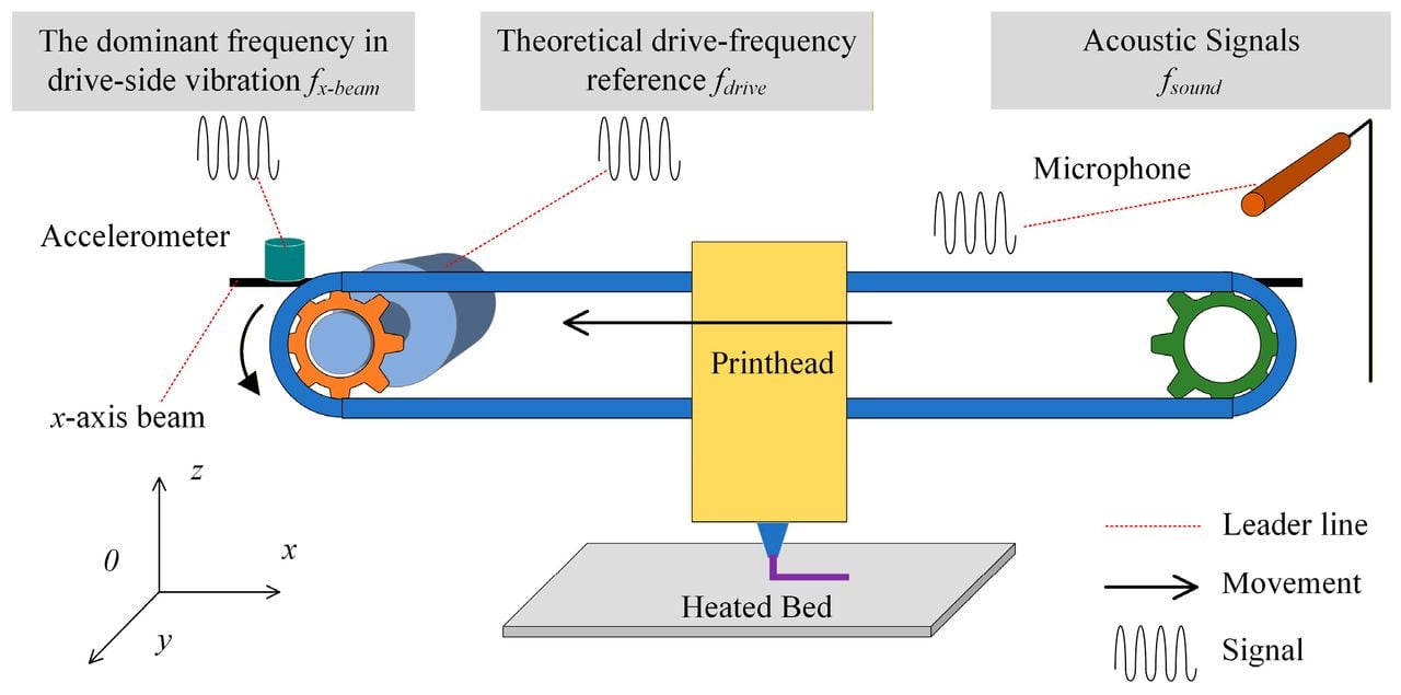
The study describes this as an electromechanical coupling problem. The researchers derive a mapping between steady-state linear velocity and steady excitation frequency for desktop FFF systems.
Practically, this could be tested by printing constant-speed segments at different feedrates, while measuring the printer’s response with an accelerometer, microphone, or even by analyzing the resulting surface ripples. Peaks in vibration or surface error would indicate resonant behavior.
The interesting part is not that stepper motion can cause vibration. That is not new.
The interesting part is the attempt to produce a formal, testable map between commanded speed and the frequencies being excited. That could make calibration faster and less mysterious.
This sounds great, but it is not magic.
The model is based on steady-state motion. Actual 3D printing is a lot of starts, stops, corners, junctions, pressure changes, and accelerations. Many of the worst artifacts appear during those transitions, not during long, clean, constant-velocity moves.
CoreXY and H-bot machines add another complication, because motor motion does not map as simply to toolhead motion as it does on a basic Cartesian axis. Extruders can also introduce their own vibration sources.
Then there are the usual mechanical variables: belt tension, frame stiffness, carriage mass, bearing condition, toolhead weight, chamber temperature, and whatever the user has bolted onto the machine since last calibration.
So this mapping should probably be seen as a calibration aid, not a universal law that permanently describes a printer.
Nevertheless, this is a very interesting concept.
Why? Because slicers and firmware already think in terms of speed.
If a printer can identify speed ranges that excite bad vibration, software could respond in two ways. It could avoid those speeds during path planning, or it could use that information to tune input shaping more efficiently.
That could matter for users who want high-speed printing without spending an afternoon attaching accelerometers and running calibration routines. It could also be important for schools, service bureaus, and print farms, where the goal is not to win print speed contests, but to keep a print farm producing acceptable parts with minimum hassle.
Manufacturers could also use this approach in factory quality control. For example, a short speed sweep might reveal whether a machine’s belts, frame, or gantry assembly are behaving as expected before shipment.
Avoiding certain speed bands may reduce maximum theoretical throughput. But in real workflows, a slightly slower print that comes out clean is often completed before a faster one that needs to be reprinted.
A big moment for this concept would be firmware integration. If this becomes a calibration wizard in Klipper, Marlin, or vendor firmware, then the concept moves from research paper to practical tool.
And if companies such as Prusa Research, Bambu Lab, Creality, or others begin using speed-frequency mapping in auto-tuning features, that would suggest the idea generalizes beyond just research.
For now, the takeaway is simple: high-speed 3D printing is not just about velocity. It is also about what that velocity does to the machine in frequency terms.
Via Machines