
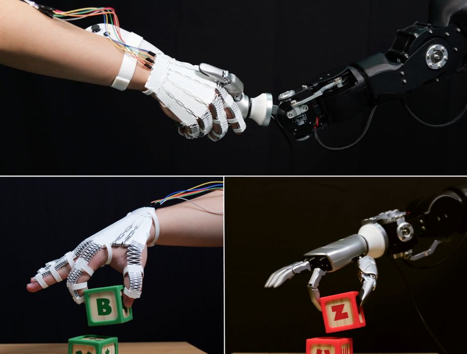
MIT CSAIL and Tianjin University researchers have devised a way to print flexible joints that know how they are bending.
The project, called X-Hinges, targets a common problem in functional 3D printing. It is relatively easy to print a flexible TPU mechanism, and possible to add a sensor afterward, but that usually means manual assembly, wires, adhesives, extra bulk, and altered mechanical behavior.
X-Hinges places the sensing function inside the compliant mechanism during a single multi-material FFF print. The researchers demonstrated a teleoperation glove, an orca shaped game controller, a foldable lamp, and a tactile sensing matrix.
A designer could potentially place a sensing hinge inside a custom gripper, wearable, interactive model, or robotic appendage without designing a separate sensor package around it.
Three Materials Solve A Signal Problem
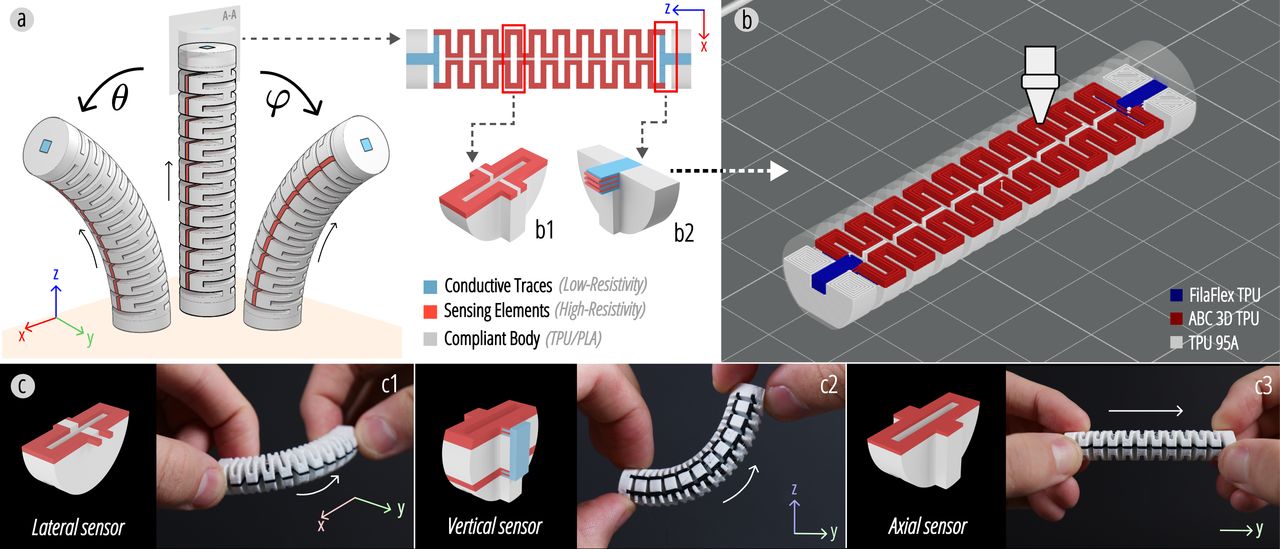
The structure uses nonconductive TPU for the flexible body, a high resistance conductive TPU for the sensing elements, and a lower resistance conductive filament for the traces. The high resistance segments change resistance as they stretch or twist. The low resistance paths carry that signal without contributing as much unwanted variation when the surrounding object flexes.
A single conductive path gives a scalar resistance reading: it may tell you that something deformed, but not reliably indicate whether a joint bent sideways, bent vertically, or compressed along its axis.
X-Hinges uses separate physical sensing layouts for those three motions. Paired sensing elements on opposite sides of a joint can be read differentially, similar in principle to a Wheatstone bridge. Signals common to both sides tend to cancel, leaving the desired bending signal more visible.
The researchers report cross axis interference as low as 8.2% in individual tests. In an integrated three degree of freedom prototype, their temporal convolutional network decoded lateral and vertical bend with mean absolute errors of 7.35 and 6.59 degrees, plus axial displacement with 1.35 mm error.
In other words, the printed part is doing some of the signal separation through geometry before software attempts to interpret the data. That is a much better starting point than asking machine learning to untangle a completely ambiguous sensor layout.
The team also built a Rhino and Grasshopper design tool that generates compliant geometry, selectively constrains unwanted motion, and inserts the appropriate sensing configuration. It exports a 3MF file with assigned material regions for slicing. The paper says the approach should work on consumer grade multi-material machines including the Prusa XL, Bambu H2D, and Snapmaker U1.
Many experiments in printed electronics depend on exotic inks, laboratory equipment, or elaborate post-processing. Here, the material requirement is more approachable: a printer capable of reliably managing three filaments, including flexible conductive TPU.
The printed hinge is only part of a sensing system. X-Hinges also needs a custom current measurement PCB, electrical connections, and a trained decoding model. Each newly printed instance has resistance variation from material batches, print settings, and tolerances.
The proposed answer is camera assisted calibration using co-printed AprilTag markers. Training a base model for a new one degree of freedom geometry took roughly eight minutes, while subsequent copies needed a two minute calibration run. That is reasonable for a lab prototype, but probably too much for most 3D printer operators.
The researchers ran one specimen through 420,000 cycles over 233 hours without visible failure, with mean resistance fluctuating below 5.5%. They nevertheless recommend periodic recalibration for precision work.
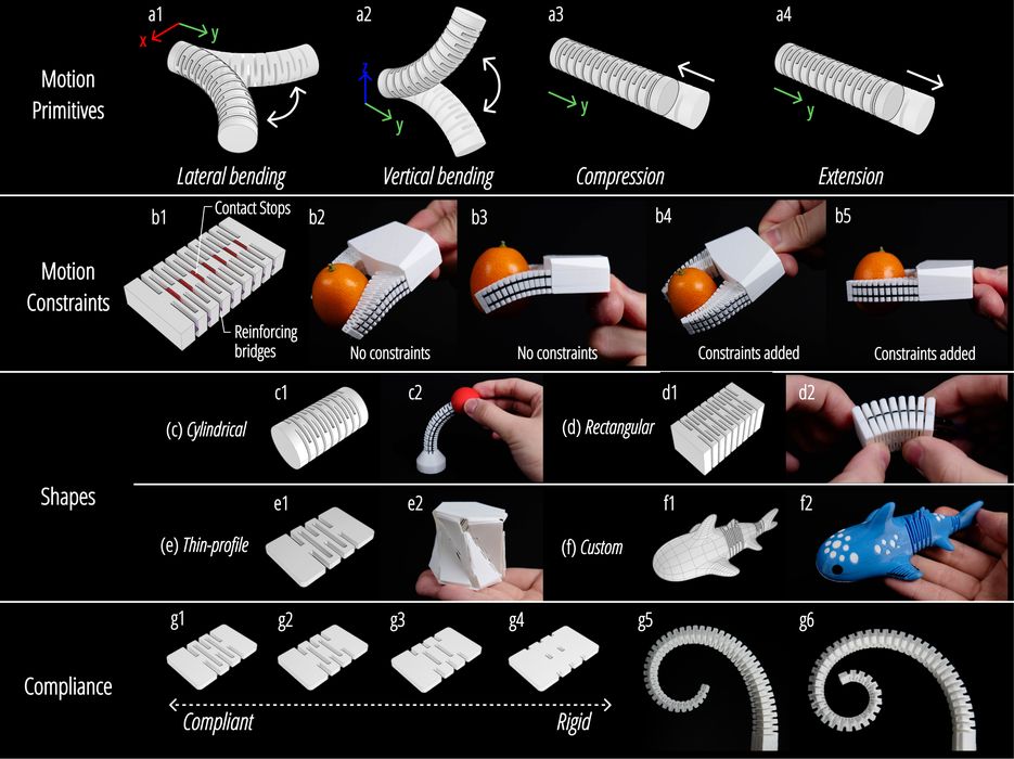
The most interesting commercial direction may be custom robotics and assistive interfaces, where a customized shape and integrated sensing could be worth more than a generic off the shelf component.
Via arXiv