

A 3D printed flexible hinge can report how it’s bending.
That’s “X-Hinges”, a 3D printing technique developed by researchers at MIT CSAIL, Tianjin University and Zhejiang University. They produced compliant joints that can detect movement in three directions without requiring conventional sensors to be attached afterward.
The trick is to make the hinge itself part of an electrical circuit.
The researchers used three filaments in a single multi-material FFF print. One is ordinary nonconductive TPU, which forms the flexible body. The other two are conductive materials, but with dramatically different electrical resistance.
A highly resistive conductive TPU forms the sensing elements. When the hinge bends or stretches, these elements deform, changing their resistance. A second conductive filament, roughly a thousand times more conductive, carries the electrical signals away without contributing much interference of its own.
The surrounding TPU also keeps fingers from touching the conductive elements and disturbing the measurements.
But there’s another problem. A single resistance measurement doesn’t tell you whether a hinge was bent sideways, bent vertically or stretched along its length.
X-Hinges addresses this through the placement of the printed sensors. Pairs of sensing elements positioned on opposite sides of the joint respond differently when the structure bends. Comparing their electrical signals helps cancel unrelated movements. A centrally positioned element responds primarily to stretching and compression.
The joint can therefore sense three degrees of freedom, although the signals aren’t perfectly independent.
To interpret the tiny resistance changes, the team built dedicated electronics and trained a machine learning model using recorded movements. In tests on one integrated three-axis prototype, the system estimated lateral and vertical bending with average errors of 7.35 and 6.59 degrees, respectively. Axial displacement had an average error of 1.35mm.
The team also created a Rhino-based design tool that lets someone choose the joint’s shape, stiffness and allowed directions of movement. It automatically arranges the conductive elements and produces a multi-material 3MF file ready for 3D print slicing.
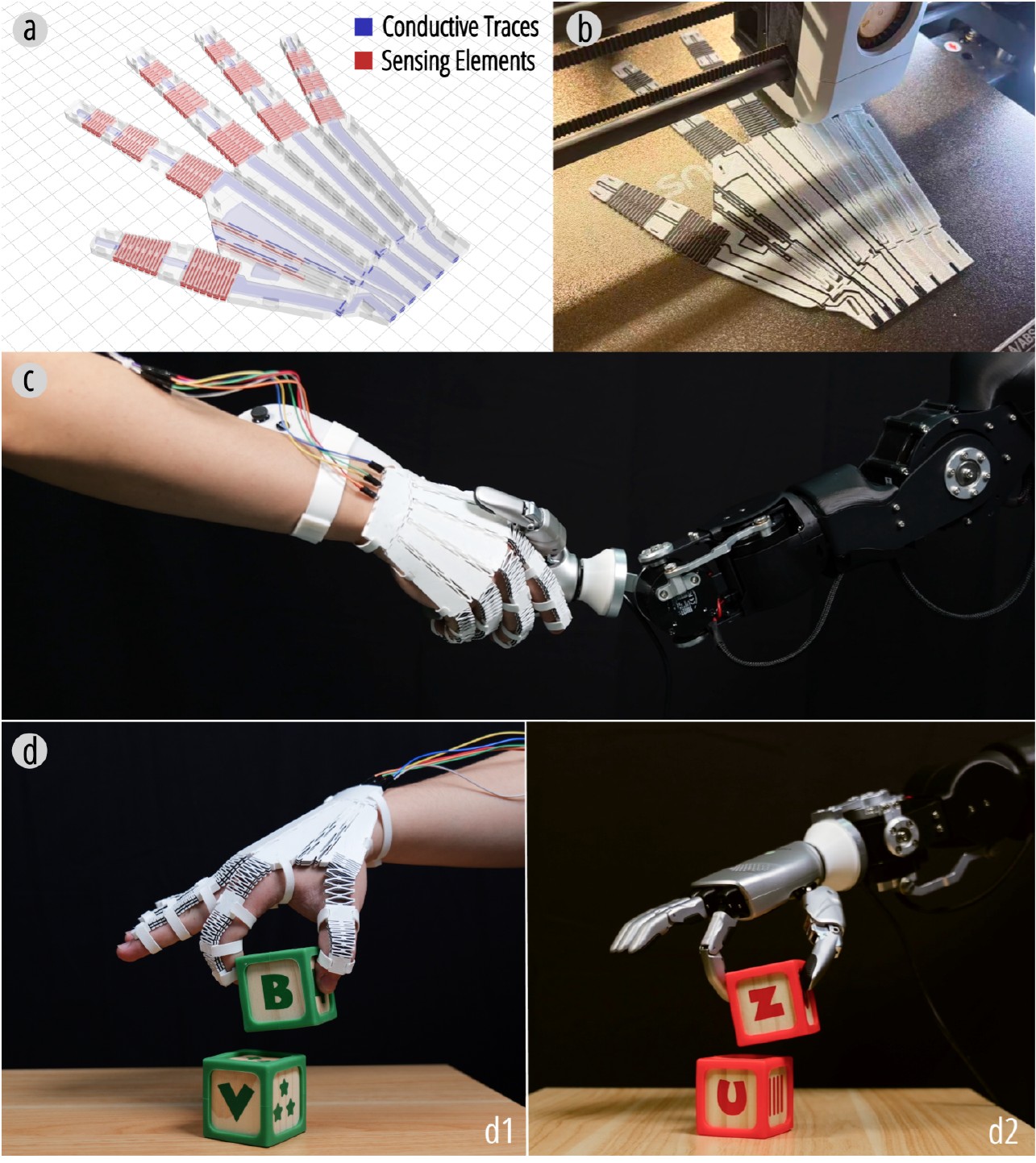
They demonstrated the idea in several objects. A printed glove tracked finger movements to control a robotic hand. An orca-shaped game controller responded to movements of its fins and tail. A folding lamp dimmed as it was compressed.
There’s some durability evidence, too. One test specimen survived 420,000 bending cycles without visible failure, although its electrical resistance still fluctuated somewhat.
Printed conductive materials don’t behave identically from one build to another, and their electrical response can drift with use. The researchers found that a motion model trained on one specimen did not transfer accurately to another. Their solution was to use a camera to track the hinge while it was moved, collecting calibration data for the model.
For previously established single-axis designs, that calibration took about two minutes per new print. The three-axis approach has not yet been demonstrated across different printed copies and geometries.
And while the sensing elements are printed in place, the device still needs external electronics, wiring and calibration.
Multi-material FFF is usually all about colors and mechanical properties. Here, the materials allow the printed part to report its own behavior.
Via ACM UIST 2026