
A carbon-fiber PETG patrt can become stronger when more material is added, but that doesn’t make it better at carrying a load.
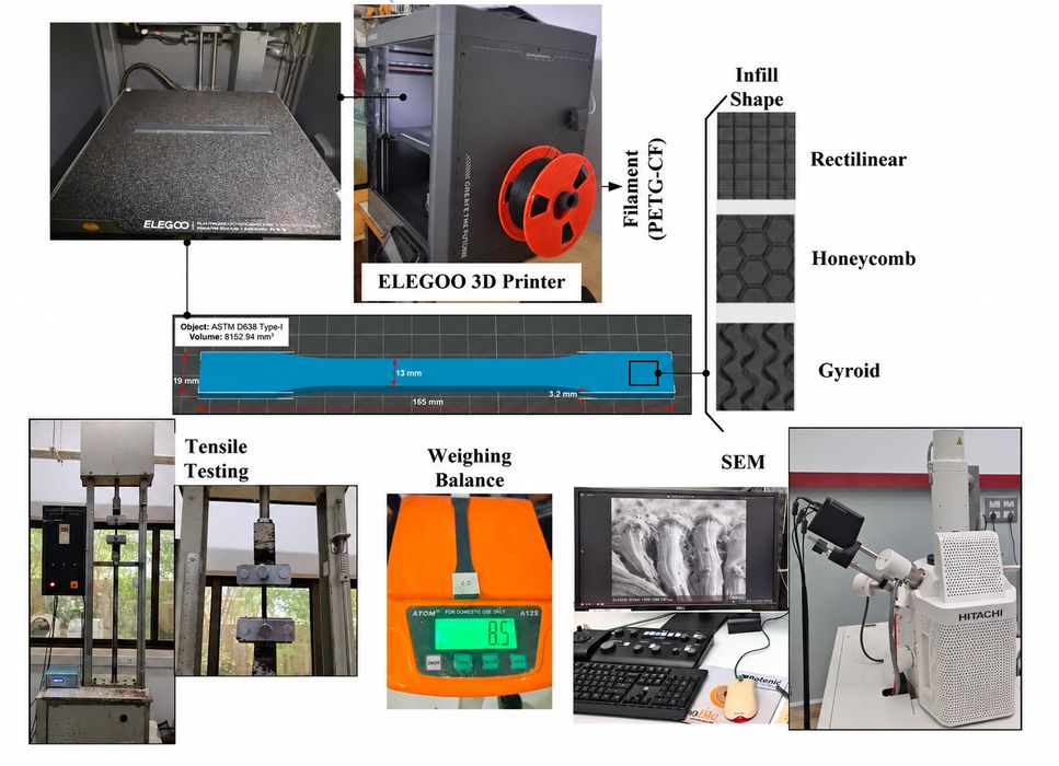
That is the surprise in a University of Johannesburg study of FFF-printed PETG-CF. The researchers varied infill shape, print speed, layer height, infill density and raster angle, then tested the resulting tensile specimens. They tracked two outcomes: tensile strength, and specific strength, which divides strength by density.
In the first 27-run matrix, the strongest specimen reached 24.38 MPa. It used a honeycomb infill, 90% infill density, 220 mm/s print speed, 0.12 mm layer height and a 45° raster angle.
The highest specific strength was 20.98 MPa·cm³/g, but that result came from a different honeycomb specimen printed at 70% infill density, with a 0.28 mm layer height and a 0° raster angle. The best absolute strength and the best use of material did not arrive together.
The PETG-CF filament contained 10 wt.% short carbon fiber. The team printed ASTM D638 Type I tensile specimens on an FFF machine, using the same filament spool and a 255C nozzle temperature. A Taguchi L27 design tested 27 parameter combinations, with one specimen fabricated and tested for each condition.
The results show why a slicer preset can’t be judged by a single measurement. For tensile strength, the analysis assigned the largest contributions to infill shape and infill density. For specific strength, infill shape and print speed mattered most, while infill density contributed almost nothing within the tested range.
Increasing infill still made the parts stronger in absolute terms. It also made them heavier. Once the researchers normalized strength by density, much of that gain disappeared.
The microscope images help explain what was happening. The higher-strength specimens showed better continuity between layers, polymer fibrillation and fewer large defects. The weakest gyroid specimen, at 14.48 MPa, showed larger cavities, interlayer separation, exposed fibers and more fiber debonding. A crack could travel along a weak interface instead of forcing its way through the surrounding material.
The researchers then combined the best individual parameter levels and ran confirmation tests. The tensile-strength setting produced 26.538 MPa, an 8.85% improvement over the best original result. The specific-strength setting reached 21.22 MPa·cm³/g, only 1.14% above the best original result.
That gap suggests there is more room to optimize for raw strength than for strength-to-mass efficiency, at least within this process window.
For the 3D printing industry, the point is that “strongest” and “most material-efficient” are different slicer objectives. A part that must handle a high tensile load may justify 90% infill. A lightweight bracket may get a better balance from lower infill density and aligned extrusions.
The next challenge is turning a good test recipe into a dependable set of print parameters that can be actually used by operators.
Via IOP Science