
![We review the Prusa MMU2S multi-material upgrade [Source: Fabbaloo]](https://fabbaloo.com/wp-content/uploads/2020/05/image-asset_img_5eb08bc469bd2.jpg)
This is part 2 of a 3 part series on using the Prusa Research MMU2S multi-material upgrade. You can find part 1 here and part 3 here.
MMU2 Spool Holders
![Default spool holders that come with the Prusa MMU2S multi-material upgrade [Source: Fabbaloo]](https://fabbaloo.com/wp-content/uploads/2020/05/mmu-assembly-original-spoolholders-1_img_5eb08bc490985.jpg)
The first problem I encountered was with the factory-designed spool storage and filament management system, since any testing would require some filament to 3D print.
The intention of the stock MMU2S design was to use five of these small roller-buckets to hold spools. These include a couple of rollers with bearings to allow easy rotation. You simply plant the spool on top and it spins when required as filament is pulled.
![Lightweight filament spool being pulled off the not-so-great Prusa MMU2S spool holders [Source: Fabbaloo]](https://fabbaloo.com/wp-content/uploads/2020/05/image-asset_img_5eb08bc4b4b6d.jpg)
Except it doesn’t. As I was doing initial testing with some leftover spools with not a lot of material on them, I found they would simply be pulled off the roller-buckets instantly, spilling onto the floor sometimes. I had to swap them out for near-full spools to gain enough weight to operate the rollers properly. These spool holders simply don’t work when the filament runs low, and I had to eventually use something else as you’ll find out later.
MMU2S Buffer
![The baffling filament buffer for the Prusa MMU2S multi-material upgrade [Source: Fabbaloo]](https://fabbaloo.com/wp-content/uploads/2020/05/image-asset_img_5eb08bc4df3a8.jpg)
The second problem with the spool feeding configuration was this curious apparatus known as “the buffer”. It’s basically several plates bolted together with a bit of a gap between each, and each gap is assigned to a specific filament path. PTFE tubes would lead from the buffer to the MMU2S itself, and any loose filament would be inserted between the plates to enter the PTFE tubes at the other end.
Why have a buffer? It turns out that when a filament is swapped, it is pulled back the same length as the distance between the MMU2S and the extruder, obviously. In a normal 3D printer configuration, filament moves forward, and almost never backward except for a few millimetres during occasions retractions. Moving tens of centimeters backwards is something no spool holder (up to now) has been designed to do.
The buffer intends on keeping the “slack” filament that appears during filament swaps from getting tangled up with each other, as each filament is exclusively assigned a space between two of the plates.
This sounds like a reasonable idea, but in practice it is hopelessly impractical. I found it challenging to even find the PTFE tube ports to feed filament through. During debugging it is important to be able to manually push and pull filament up to and from the MMU2S unit, and this is essentially impossible with the buffer in the way.
Daring to accept the unknown risk of filament entanglement, I tossed the buffer aside and have never used it since. This also significantly reduces the rather large amount of table space required to use the full-five spool MMU2S configuration. Subsequently, I’ve learned those who still use the buffer can mount it vertically to save space.
MMU2S Importing Multimaterial 3D Models
Having figured out how to set up the filament spools in a usable fashion, at least for testing, I proceeded with the goal of 3D printing a cube cut into two pieces, each of which would have a different color.
For this I simply took a 20mm test cube 3D model and chopped it diagonally with a 3D print utility, creating two separate STL objects. These are imported into PrusaSlicer for preparation.
![Selecting printer modes on PrusaSlicer after the MMU2S upgrade: multi-material and “Single” modes [Source: Fabbaloo]](https://fabbaloo.com/wp-content/uploads/2020/05/mmu-printer-selection_img_5eb08bc512d55.jpg)
But wait — you must reconfigure your PrusaSlicer software to account for the “new” machine. Remember, you now have an Original Prusa MKxS MMU2S, not an Original Prusa MKxS. This activates several important features related to multi-material slicing in the software.
Importing the STL pieces into a single job must be done properly. If you simply import them one after another, the software assumes you are printing independent and separate parts. They will not be aligned and you won’t get your multi-color 3D print.
![Importing 3D models for multi-material 3D printing: wrong [Source: Fabbaloo]](https://fabbaloo.com/wp-content/uploads/2020/05/image-asset_img_5eb08bc537a62.jpg)
Instead you must import them simultaneously. This is easily done by dragging ALL of the STL pieces at once into the PrusaSlicer window with one drag operation. Then the software intelligently asks you whether these are separate or a joined object. This is most easily done if the multiple-part 3D model is stored in .3MF file format; in that case you just drop the file and it’s all automatically handled in PrusaSlicer.
![Importing 3D models for multi-material 3D printing: correct [Source: Fabbaloo]](https://fabbaloo.com/wp-content/uploads/2020/05/image-asset_img_5eb08bc55bce5.jpg)
Once in the slicer, you can select each of the segments and assign a filament to it. You can choose any of the five materials, but PrusaSlicer has no idea what is actually loaded on the 3D printer; you must manually ensure the software filament configuration matches the physical configuration, or else you will be surprised later.
![Rendering of a sliced multi-material 3D model in PrusaSlicer. Note large “purge block” used to clean out the hot end during filament swaps [Source: Fabbaloo]](https://fabbaloo.com/wp-content/uploads/2020/05/image-asset_img_5eb08bc57e394.jpg)
MMU2S Filament States
My first attempts at prints were quite confusing, and in retrospect it was because I didn’t really understand what was supposed to happen. I didn’t realize there were different “states” for the location of the filament, and how the filament was actually being moved around by the 3D printer’s firmware.
In my attempts to debug (and understand) what was going on, I would try different manual filament loading operations to simplify the situation, but this turned out to be a very bad idea, as my futile debugging activities resulted in scenarios never anticipated by the software and unexpected results occurred.
Like this:
![Confusing message after the Prusa MMU2S multi-material upgrade [Source: Fabbaloo]](https://fabbaloo.com/wp-content/uploads/2020/05/mmu-testing-badscreen-1_img_5eb08bc5a3fca.jpg)
Or this:
![Confusing message after the Prusa MMU2S multi-material upgrade [Source: Fabbaloo]](https://fabbaloo.com/wp-content/uploads/2020/05/mmu-testing-badscreen2-1_img_5eb08bc5c6859.jpg)
Or this:
![Confusing message after the Prusa MMU2S multi-material upgrade. There are only FIVE filaments [Source: Fabbaloo]](https://fabbaloo.com/wp-content/uploads/2020/05/mmu-testing-badscreen3-1_img_5eb08bc5e8366.jpg)
Or this:
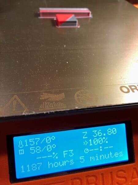
![Confusing message after the Prusa MMU2S multi-material upgrade. It did not take that long [Source: Fabbaloo]](https://fabbaloo.com/wp-content/uploads/2020/05/mmu-testing-first-print-duration-1_img_5eb08bc617897.jpg)
If you think I am the only one receiving this type of error, I have seen others posting similar images on various social media. My suspicion is that my experiments inadvertently introduced scenarios not anticipated by the firmware, causing all kinds of strange things to happen.
That might suggest I should have simply followed the instructions, but in retrospect I would never have learned what was actually going on without decomposing the relatively complex sequence of events that takes place when using the MMU2S.
This was all terribly confusing. Eventually, I learned the following, which is important for any MMU2S operator to understand:
The filament is considered “Loaded” when it’s laying across the MMU2S’ gears, ready to be engaged — but not necessarily engaged at that moment. Thus, when the control panel offers to “Load Filament”, it means it performs a test to see if it can pull a filament up to the MMU2S sensor, and then move it back to the ready position. It basically verifies there is a filament in that path that can be used.
Alternatively, the “Load Filament to Nozzle” command assumes you have a filament in the ready position. If so it then pushes it all the way down the PTFE Bowden to to the extruder. If you’re configured properly, the sensor on the extruder will see it and the gearing will bite down on the filament.
These are concepts that are different from what you might experience on a standard 3D printer, where automated filament loading isn’t available. While they make a lot of sense explaining it like I’ve just done, the problem is when they are not in the expected state when you try to do things. This is new and in my opinion, not properly explained by Prusa Research. But I (and everyone) eventually figures it out.
There are some very confusing elements to the MMU2S as well. For example, in the “Selector”, there is a sharp blade that is supposed to cut off the used tips of filament as it slides by. However, in practice it simply doesn’t work and it appears that the software is not even attempting to do so. Why install a blade at all then?
This is part 2 of a 3 part series on using the Prusa Research MMU2S multi-material upgrade. You can find part 1 here and part 3 here.
Via Prusa Research