
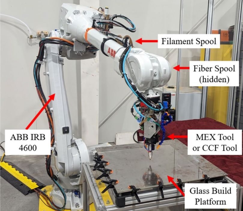
A new multi axis continuous carbon fiber extrusion tool aims to make “fiber steering” practical, not just impressive in demos.
Continuous fiber reinforced material extrusion (MEX) has long promised ultra high strength along the deposition direction, but it is notoriously awkward to deploy in anything but simple, uninterrupted paths. The moment you need travel moves, corners, or multi axis orientations, the fiber becomes a literal tether between nozzle and part.
Past approaches usually trade one capability for another. Some systems vary fiber content but struggle to cut and refeed reliably. Others can cut and restart fiber, but the added mechanisms create a bulky toolhead that collides easily during multi axis motion.
In a new research paper, Virginia Tech researchers have developed a deposition tool meant to hit all three requirements at once: cut and refeed, adjust fiber volume fraction in place, and keep a slender collision volume suitable for multi axis toolpaths.
How The Tool Works
The design uses co-extrusion of a thermoplastic filament with a continuous carbon fiber towpreg feed. Towpreg is a bundle of continuous carbon fibers that has been pre-impregnated with a resin. They chose it because it has enough stiffness to survive cutting and refeeding while still letting fiber fraction vary by changing polymer flow.
The polymer feeder is built from common dual drive extruder style components, but mounted at a 40 degree angle so that the fiber can feed more vertically into the hot end and avoid bending related buckling.
Fiber handling is the “make or break” feature. A powered wheel and spring tensioned bearing push the towpreg through an alignment stack, a servo swings a blade to cut the fiber cleanly, and chamfered guides straighten the frayed cut end before it enters the co extrusion hotend. In their build, the cutter to nozzle distance is 58.5 mm, which becomes the minimum fiber length the tool can reliably deposit.
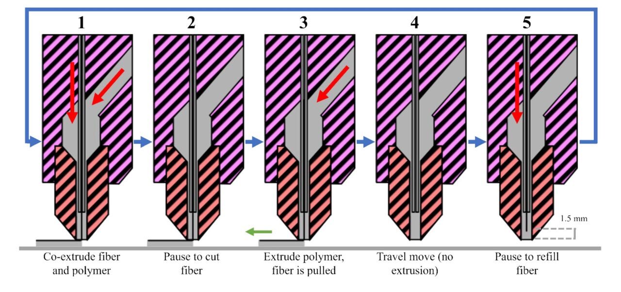
Inside the hot end, a guide tube feeds the towpreg into the center of the molten polymer so the two exit together. The researchers found they could achieve reliable printing with 1.75mm PLA filament at a slow 5mm/s, with the guide tube ending about 1.5 to 5.0 mm above the nozzle tip.
They also deliberately start flow with the fiber slightly shy of the nozzle exit (about 1.5mm) so the polymer leads and helps pull the fiber straight, reducing clogs.
Reliability, Collision, And Strength
Regarding reliability, the team printed a 100 x 150 mm plaque that forced 426 consecutive cut and refeed cycles, and reported a 100% success rate without clogging. That is a pretty big deal for anyone who has fought intermittent fiber restarts on some continuous fiber systems.
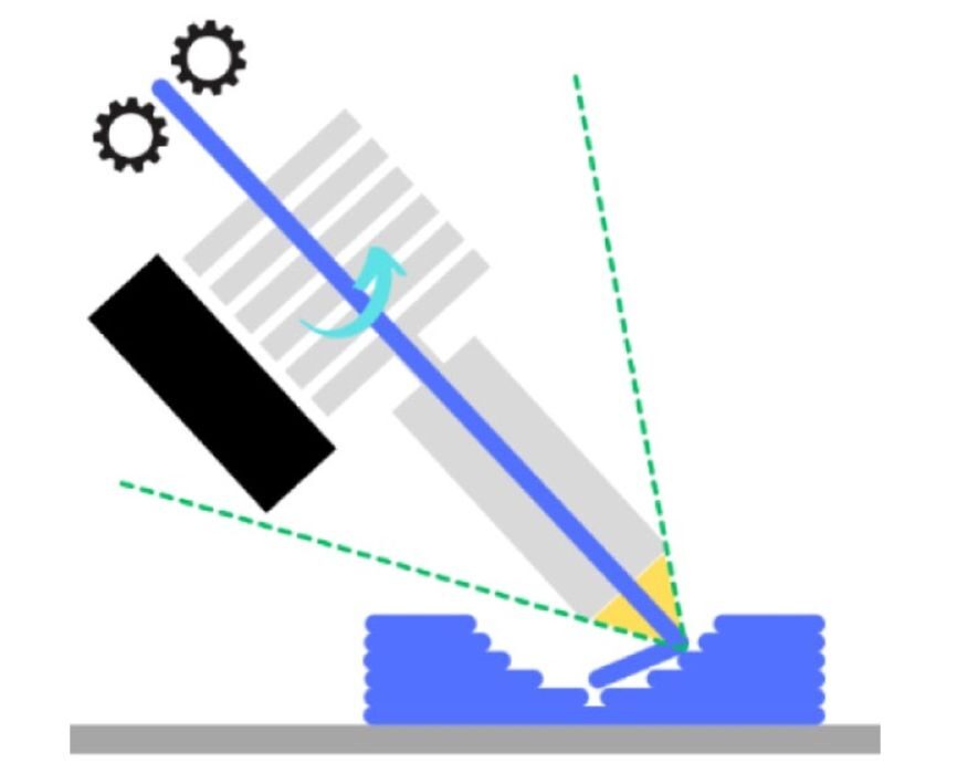
For multi axis practicality, they model the collision envelope as a cone around the nozzle. The full tool achieved a collision cone of 56.2 degrees from the tool’s primary axis, and the hot end alone could reach 41.6 degrees, showing how much geometry flexibility depends on where larger components are positioned relative to the nozzle.
Along the fiber direction, their continuous carbon fiber PLA reached about 191 MPa ultimate tensile strength and 10 GPa tensile modulus, versus about 60 MPa and 3 GPa for neat PLA, and about 57 MPa and 4.3 GPa for short carbon fiber PLA.
The twist is how severe the penalties were when away from the fiber direction. Compared with neat PLA, the continuous fiber composite saw large drops in intra layer and inter layer tensile properties, consistent with weak interfaces and void driven defects. SEM images showed substantial fiber pull out and little to no impregnation of the PLA matrix into the fiber, which the authors flag as a key improvement target.
Why Multi Axis Helps, And What Could Still Go Wrong
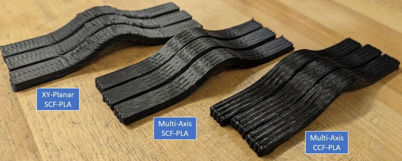
To show why multi axis matters, the team printed a curved tensile bar designed to impose non planar load paths. A multi axis short fiber toolpath improved maximum load by 41.6% compared to a conventional XY planar short fiber build. But the multi axis continuous fiber version jumped dramatically, with average maximum load about 4520.66 N versus about 550.92 N for the planar short fiber baseline.
That kind of delta is exactly why “aligning anisotropy to the load path” is so important. Still, the failure behavior hints at the adoption risk: if fiber matrix bonding is inconsistent, you can get variability, progressive straightening, and then sudden failure when the interface gives up. In other words, their tool can place fiber where you want it, but the materials science still decides how reliably that fiber carries load.
The most valuable follow up will be process tuning and toolpath automation: longer fiber polymer interaction times, alternative fiber sizing compatible with the matrix, and multi axis toolpath planners that place cuts and restarts where they don’t corrupt tight corners.
If those pieces are sorted out, multi axis continuous fiber MEX starts looking less like a lab experiment and more like a composite manufacturing option. However, we will still have to wait for someone to commercialize the technology.
In the meantime, consider taking a read through this interesting paper, as it shows a number of mechanical innovations for improving continuous carbon fiber 3D printing.
Via The International Journal of Advanced Manufacturing Technology