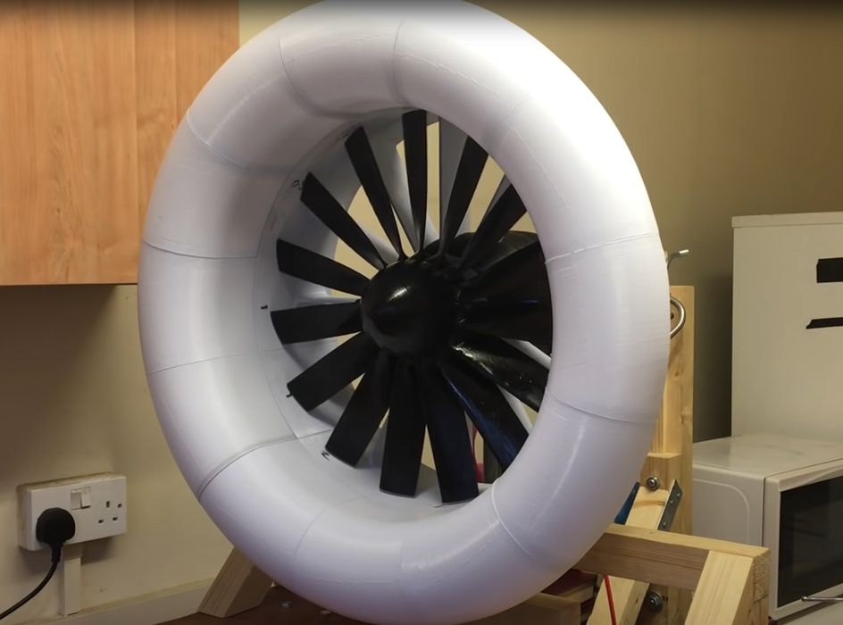
The SkyersJet Project is developing a partly 3D printed EDF system for RC aircraft, but encountered a spectacular problem during testing.
The project intends on creating a high-performance EDF engine for RC aircraft. If you’re not familiar with an “EDF”, let me explain.
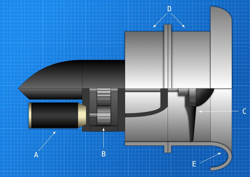
EDF, or Electric Ducted Fan, is an alternative to a standard propeller system. A standard propeller typically has 1-4 blades and rotates freely in open air. In contrast, a ducted fan includes a curved duct that funnels air into the blades, which are significantly higher in number. In the SkyersJet Project, they appear to use 16 blades.
Why build a complex EDF when standard propeller arrangements are far simpler to produce? Wikipedia explains:
“The duct reduces losses in thrust from the tips of the propeller blades, and varying the cross-section of the duct allows the designer to advantageously affect the velocity and pressure of the airflow according to Bernoulli’s principle.”
In other words, you can make a far more efficient engine with a ducted fan. The “E” part simply means the fan is powered electrically, rather than with a CO2-generating fossil engine.
There’s another factor with ducted fans: the tips of standard propellers, if rotated sufficiently fast, can exceed the speed of sound, and that’s not a good thing as the airflow is severely disrupted. Meanwhile, an EDF allows the tips to spin faster without hitting the sound barrier.
The application here is for high-speed RC aircraft, where efficient and powerful engines are required.

The SkyersJet project explains their design:
“The SkyersJet EDF system is designed to provide more efficient thrust than other existing EDF systems. In order to achieve this, the fan is much larger in diameter than other EDFs. To spin a fan this large requires a lot of torque. Normally a fan or propeller of this diameter would be mated to an outrunner motor. However, I chose an inrunner motor because they have a higher power to weight ratio and greater efficiency.”
The project 3D printed the blades in “high strength PETG” and then mounted them on a machined aluminum hub. The duct itself was 3D printed from multiple parts and then assembled.
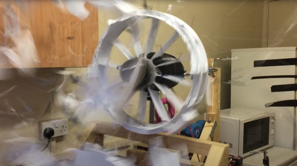
The project then undertook a testing regime and on “Thrust Test 11”, this happened:
For reference, here’s a screen-grab of the moment of action:

What happened here?
We know that EDF systems spin blades very rapidly, and the SkyersJet Project’s design increased the fan diameter. If running at the same RPM, the speed of the tips would increase proportionally.
Evidently this gigantic centrifugal force was too much for the blades to withstand, and they split. Once one blade detaches, the system becomes unbalanced and everything flies off. Blades impacting the duct basically blew it to smithereens in an instant.
While the SkyersJet Project is back to the drawing board, what can we make of this event?
It appears that the high-strength PETG was not suitable for this application. One suggestion would be to use a higher-strength material, such as a composite with chopped carbon fiber.
For even greater strength, a continuous carbon fiber 3D print could be attempted. If the fibers were lain along the length of the blade, they could add very significant strength to the blade.
The project does not explain how the 3D prints were made. It would be significantly advantageous to orient the 3D print so that the extrusion lines aligned with the longer axis of the blade. This would provide maximum strength along that axis. However, if the blades were 3D printed vertically, they would certainly delaminate along the layer lines.
While this failure was certainly spectacular, it shows how simple design and material decisions can dramatically affect the results of a project. On the other hand, even when building this design with appropriate materials and processes, you’d still want to “test to destruction” to understand how strong it really could be when used.
