
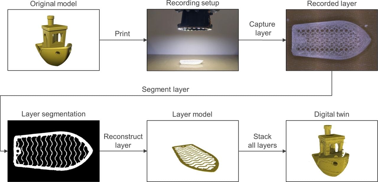
Researchers demonstrated a low cost, camera driven way to build a high resolution digital twin of every FFF print layer.
The idea is straightforward, but powerful: capture a high resolution image immediately after each layer is printed, segment only the fresh material, and extrude those masks to reconstruct the part. In other words, turn a standard FFF job into a verifiable digital twin as it builds, without CT scans or expensive 3D sensors.
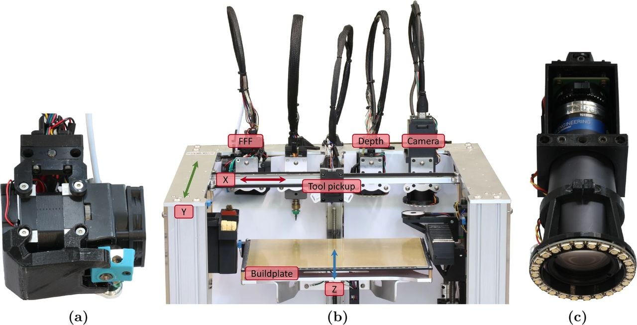
A team at Universität Hamburg modified an E3D ToolChanger desktop FFF 3D printer with a telecentric RGB camera and RGBW ring light, controlled via OctoPrint and custom tooling. They tried a RealSense D405 depth camera but dropped it after seeing up to 1 mm depth error in practice — not nearly enough to separate successive layers reliably.
Layer By Layer Imaging On Accessible Hardware
The system parks the extruder, picks up a dedicated camera tool (hence the use of the toolchanger), and tiles the layer with multiple images because the field of view is small. They tested uniform white, four directional white, and tri-directional red, green, blue illumination. A U-Net++ segmentation network receives the current image and the previous-layer image for context, and isolates only the newly deposited roads.
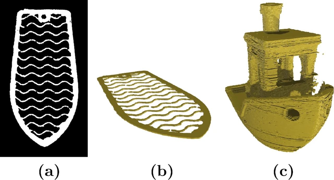
On their validation set, the best input — the tri-directional RGB lighting — reached an intersection over union of 0.94. More importantly, the model generalized: prints not seen in training, including a translucent PLA Benchy, scored around 0.82 IoU and showed the network tracking the actually printed features, seams and even missing material, rather than just GCODE intent.
Once segmented, each layer image is cleaned, vectorized, and extruded to the layer height from the GCODE, then stacked into a single STL. That preserves internal structures like infill and voids — the parts CT would normally reveal — and enables downstream checks for geometry, stress analysis, and documentation.
Digital Twins With Surprising Fidelity
The team quantified dimensional error using test coupons and calipers across colors and orientations. The mean absolute offset between the physical parts and the reconstructed twins was 58.2 microns. That number combines camera positioning, segmentation, stitching, and measurement uncertainty — and is small enough to matter for serious QA, even if it does not certify every feature to that tolerance.
A clever “recursive” trial repeatedly reprinted an Ultimaker Robot by using the reconstructed twin of the previous print as the next build file. Fine details softened up over iterations, but shape and features largely survived three cycles, suggesting this pipeline keeps a lot of real geometry, not just toolpaths.
The Catch: Throughput And Blind Spots
This sounds great, but there is a notable time penalty. On their setup, layer documentation added a whopping 132 seconds per layer when taking six images per position, or 43.5 seconds when taking one image. A #3DBenchy that normally prints in 93 minutes stretched to 437 minutes (!) with the full lighting sweep, or 210 minutes with single-pattern capture — a 4.7x or 2.3x slowdown, respectively.
There are also inherent limits. The method is top-down only, so it will not see Z-axis adhesion issues, droop under overhangs, or warping unless those artifacts present on the layer surface. It assumes GCODE layer heights for extrusion in reconstruction, meaning true Z deviations are not measured. And large, high-detail meshes balloon file sizes, though slicer simplification helps.
Why This Could Matter
Reliable, inexpensive, layer-wise geometry capture would be a big step for polymer AM. Service bureaus could document jobs, OEMs could prove as-printed features, and labs could finally close the loop by adjusting parameters when the model deviates. Because the hardware bill is modest — a telecentric lens is not cheap, but it beats structured light rigs or CT — this approach could be within reach for many shops.
If they can make the camera operate faster, FFF might finally get a cheap QA system.