
A newly published patent from Flashforge describes a filament cutting mechanism that stays out of the build area until the instant it is needed.
Most FFF machines that cut filament do it with a fixed “post” or striker parked at a bed corner. The toolhead drives into that post to actuate a blade lever and shear the strand, often as part of color change, multi material purging, or a tool change routine. The problem is mundane but incredibly important: even a small protruding cutter element lives inside the printable envelope. On compact printers, that lost corner can matter, and on faster machines it might also adds collision risk and routing constraints for the motion planner.
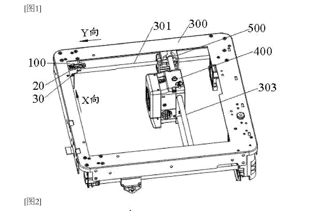
The patent’s premise is that the cutter post does not need to exist in the print zone at all times. Instead, the mechanism mounts in the frame surrounding the build plate. In the “rest” state, the cutter top rod hides outside the printable region, aligned along a first horizontal direction. When a cut is required, a linkage rotates that rod into the build area, now aligned along a second horizontal direction, so the toolhead’s cutter lever can contact it. After the cut, the rod retracts back out of the build envelope.
Reclaiming Bed Space From Filament Cutters
This is not a new “process” so much as a housekeeping upgrade to a common feature. Filament cutters are now routine in multi material ecosystems, and they show up on toolchangers as well. Any design that reduces dead zones and removes fixed obstacles can translate into a more honest build volume, fewer firmware guardrails, and simpler mechanical packaging around the bed.
The document also hints at an efficiency angle. If the printer can combine motions to deploy the cutter while already moving the carriage toward the cutting position, cycle time shrinks slightly. That is not a headline throughput number, but in a production setting where a machine performs many swaps per job, small time cuts can add up.
A Mechanical Trick With Some Buffering
The mechanism is clever because it tries to avoid adding new actuators. One described option uses a moving “impact” assembly that rides on an axis rail. That assembly strikes a sliding block (a bumper) that protrudes from the frame. When hit, the block retracts along the first direction and drives a gear rack. The rack turns a buffering gear, which rotates the cutter top rod around a vertical shaft and swings it into the print area.
There is also a description of what happens at end of travel. The patent describes slanted buffer faces and a cam like disengagement that decouples the gear from the rod once the rod reaches its deployed position. In plain terms, if the motion system overshoots slightly, the extra force is absorbed mechanically rather than stalling a stepper and losing steps. That is a very practical detail for high acceleration machines.
Return to the hidden state can happen by a spring, a torsion spring on the pivot, or by intentionally running the carriage back past the mechanism to “bump” it into reset. The patent even suggests making the whole module removable via a mounting block, which would matter if the cutter could wear out or needs occasional cleaning.
The patent does not quantify the reclaimed printable area, which will depend entirely on how much corner real estate typical cutters consume in the target machine. Debris management is another open question; cutters create small filament chips that can migrate into belts or linear rails if not contained.
If Flashforge adopts this technology, the competitive value is pretty subtle but possibly meaningful in a marketing sense: “full build volume” claims become easier to justify, and the machine gains a cleaner motion envelope for faster travel moves. It could also be important if a future desired feature is a small machine footprint.
In the end, this is classic 3D printer evolution: not a new material or a new slicer trick, but a mechanical detail that removes a long accepted annoyance — and those are usually the things users notice every day.
Via WIPO PATENTSCOPE