
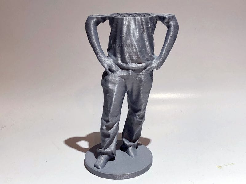

When 3D printing failure is a looming presence, but it’s appearance can be limited by taking several key steps.
In woodworking you’ll often hear the rule, “measure twice, cut once”. That particular rule is not really usable in 3D printing, but there are some other measures you can take to ensure success. Well, perhaps not “ensure” success, but at least maximize the possibility of success.
These are based on my personal experience using a variety of 3D printers and 3D printing software. In other words, I’ve made a TON of mistakes and want to tell you how not to make the same ones.
When I’m approaching a 3D print job, these are my major rules of thumb. I don’t get success on every 3D print, but I have certainly reduced my failure rate.
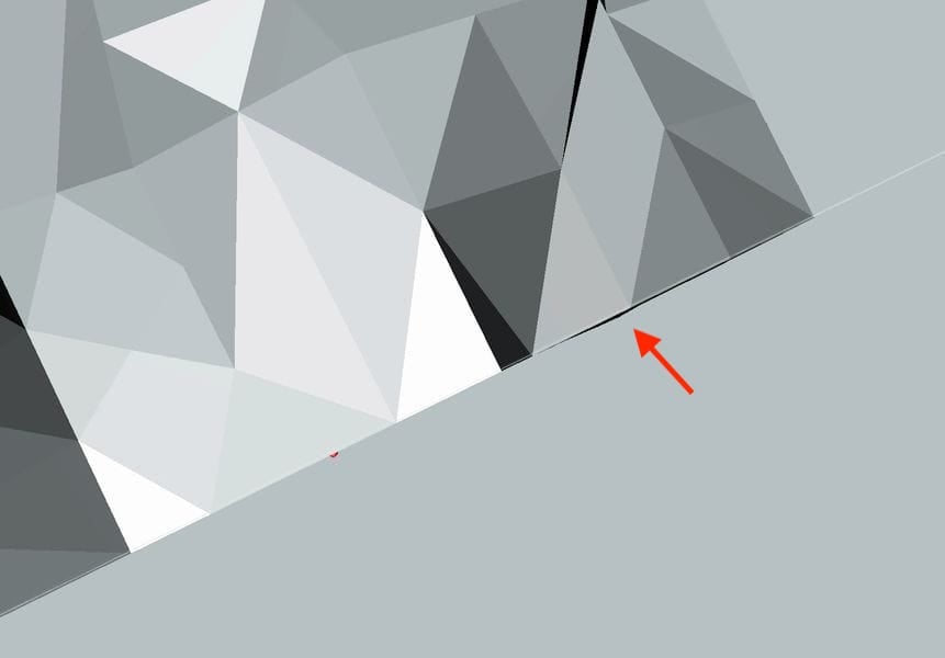
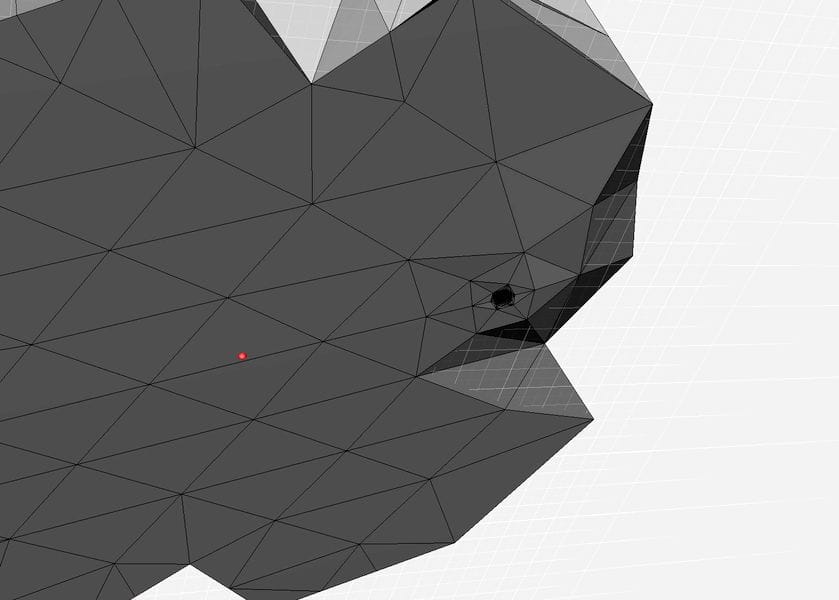
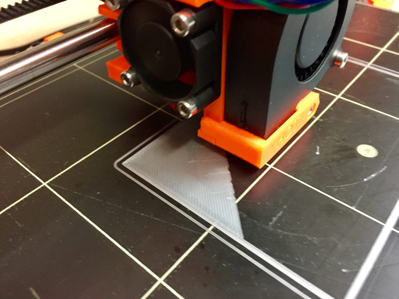
3D Model is Flat: Sometimes prints don’t stick at all, and it can be quite mysterious. A 3D model with a seemingly flat bottom should adhere well, especially if the bed is level and z-gap is adjusted. But those measures can e entirely messed up if the bottom of your 3D model is actually not flat. Perhaps it merely LOOKS flat, but is not ACTUALLY flat.
I’ve had this scenario many times, particularly when I’m in a rush and don’t bother to check. In this scenario, only a small portion of a large flat area prints on the first layer due to the non-flatness. It may be there’s only a small bump on an otherwise flat surface – and that bump becomes the first layer.
This effect can also occur if your 3D model is not quite level.
The solution: chop off a minor portion of the bottom of the 3D model with a plane cut using your favorite 3D modeling tool. Only then will you be truly ensured to be flat and stick well.
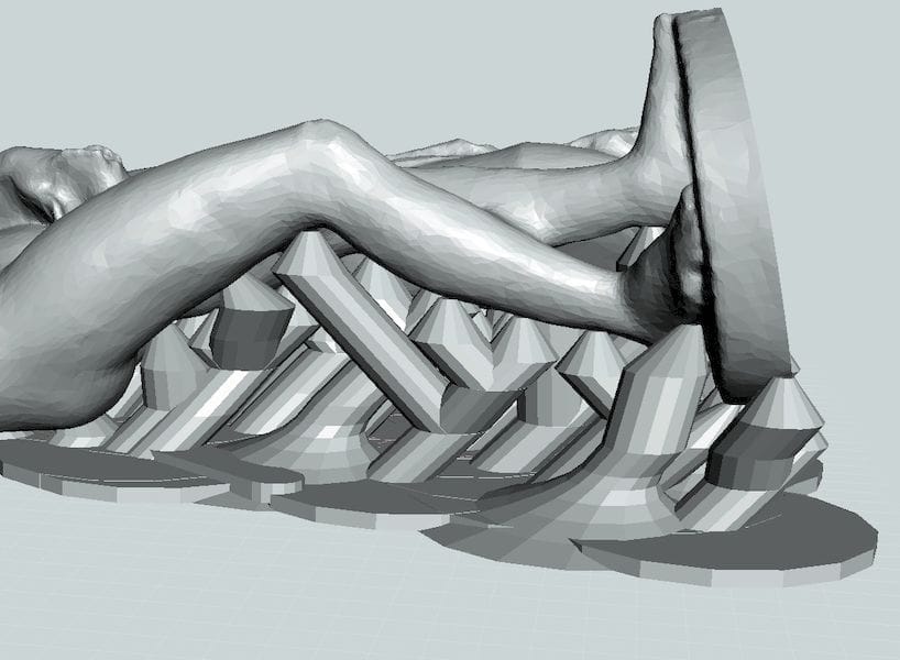
Support Strategy Selected: Every 3D model has slight different geometry, and in many cases support structures should be used. Based on the capabilities of your equipment, you should have a sense for when this is so. If you don’t use sufficient support structures and material, you may find portions of your 3D print droopy, failed and even missing.
The solution is to examine the geometry carefully and decide on the orientation and degree of support structure required. You may choose to generate supports in your favorite slicing software, but depending on the nature of the 3D model you may also choose an alternate style of support structures generated elsewhere. One popular option here is using MeshMixer to not only analyze overhangs, but also generate a different style of supports.
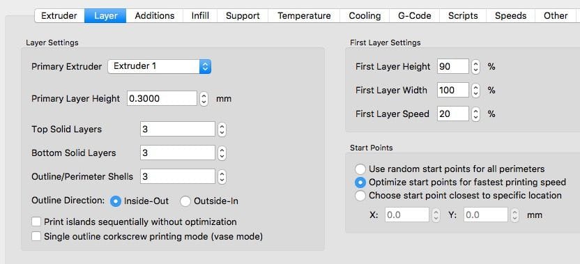
Basic Slicing Parameters Correct: This one goes without saying, but make sure you have the key slicing parameters correct. If you’re not paying attention, you may end up with the printing parameters used in the previous print job, and they may not match what you require for this job.
Do you have the right layer size? What infill density is set? Did you leave “Vase Mode” on from the previous job? And so on.
The solution here is to simply – and quickly – go through each and every parameter to ensure it is correct.
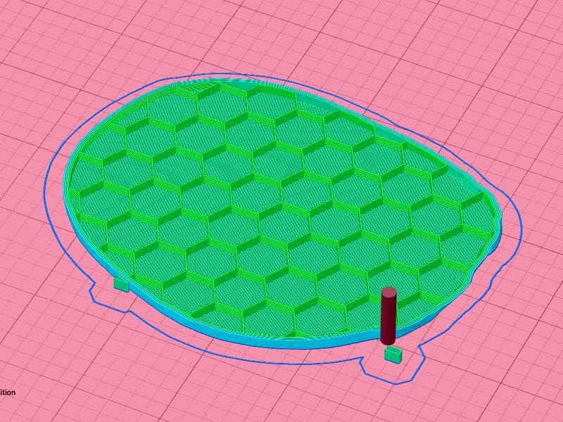
GCODE Checks Out: 3D print jobs sometimes go awry at the slicing stage, and if you don’t review it beforehand you may find a problem – too late.
The solution here is to use your 3D slicing software’s visualization feature to give the generated toolpath a “once over”. If there are problems you can very often see them through the visualization. You may see a poor first layer, or missing segments, or thin areas that simply don’t appear at all. Always review your GCODE before proceeding.
Matching Material: Did you select the desired 3D print material in your slicing software? Does your machine have that material loaded? It might not be pretty if there is a mismatch.
For some 3D printing systems the machines themselves perform this check, but it only works when proprietary material systems are deployed. In many cases, however, open materials machines can permit this mistake to occur.
The solution is quite straightforward: make sure both your slicing software has selected the desired material, and that same material is actually loaded on your equipment.
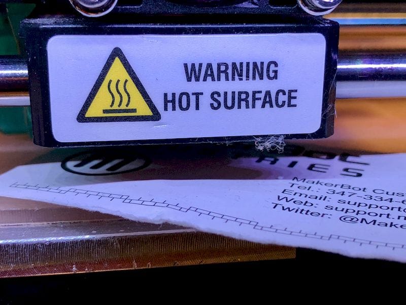
Level the Bed: Many 3D print failures occur due to poor bed adhesion, and those are caused frequently by an unlevel print surface. While many current 3D printers do now include an automated leveling procedure, not all do, and you must take on this responsibility yourself.
Sometimes the print surface is removable, and this can complicate this issue. Should the replaceable bed be slightly askew, you may think the bed is level, but it is in fact not level.
The solution is to ensure the bed is level and that your removable print surface is correctly installed.
Z-Gap Set Correctly: One of the most critical factors is getting the gap between your nozzle and print surface set correctly. If too tight the extruder may jam due to the excessive pressure required to push thermoplastic through the tiny gap between the nozzle and the bed. If too loose the thermoplastic will adhere poorly and likely cause a print failure later when the massive print has insufficient material holding it down. If you’re lucky your equipment will automatically set this, but very often machines do not.
The solution is to periodically check your z-gap and adjust accordingly. This is usually a very simply procedure on your machine, sometimes combined with the leveling procedure.
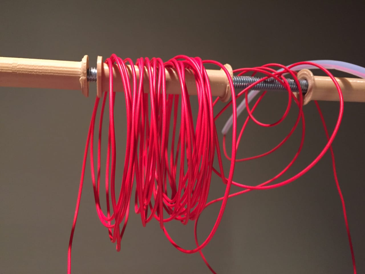
Spool Not Tangled: This insidiuous problem manifests itself only later on during 3D printing and thus can be quite wasteful of time and materials. The essence of the problem is that there is either a tangle in your filament that will knot up much later, or perhaps the spool is not free to rotate easily when delivering filament when pulled by the extruder.
The solutions are relatively easy here. Check for tangles by pulling out a length of filament and rewinding it. You’ll soon discover any tangles. If you find one, untangle the filament by dropping off several loops from the spool and rewinding them, as explained here.
First Layer Successful: If you’ve done all of the above, that’s good. But there is one more thing to do: make sure it works.
I do this by always observing the first layer of the print. This layer is where almost all the troubles occur, so if you have this right, then you may have a successful print. Sit and watch until the second layer begins, at the very least.
Yes, this is quite tedious, but moreso is re-running a 20-hour print. You will be surprised at how many bad prints you can detect and resolve by simply watching the first layer complete.
And those are my main tips for ensuring desktop 3D print success. Enjoy!