
A laser beam with a deliberately abrupt edge may help metal powder bed fusion produce fewer hot cracks.
That is the idea behind a recently published patent application from EOS, the well-known German AM company. The filing is about selective laser melting of crack-prone alloys, including nickel-based superalloys such as Inconel and MAR M 247, along with tungsten-molybdenum and titanium alloys.
EOS’s application, published as CN122622858A, asks for protection around how radiation intensity changes across the laser spot while the beam scans the powder bed. The basic requirement is a change of at least 1% per micrometer at some point within the spot. In this process it changes the shape of the molten region and, potentially, the solidification structure left behind.
A Wider Melt Pool With A Sharper Edge
Most LPBF systems work with a beam profile that gradually fades toward its edge. EOS proposes combining a relatively broad spot with a much steeper intensity drop near that edge. The application describes spot diameters from roughly 30 to 470 micrometers, with at least 90%, and preferably 95% or 99%, of the laser power contained inside the defined incident area.
The reason is connected to powder behavior. According to the filing, a shallow intensity gradient at the edge of a large spot can encourage powder particles to clump or partially sinter outside the main melt zone. Those unstable regions can contribute to later cracking. A sharper falloff is intended to keep the transition cleaner while retaining a relatively flat melt pool operating in conduction mode.
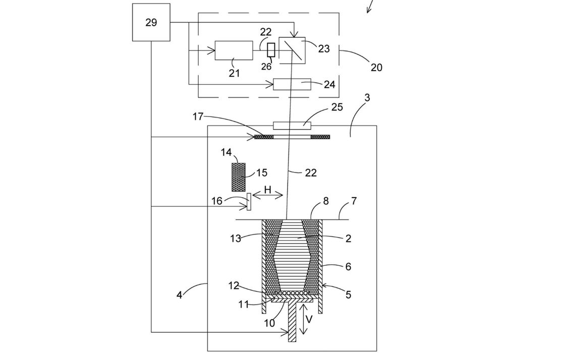
The beam does not have to be the typical round profile. The drawings show Gaussian, donut-shaped and flat-top distributions, plus an asymmetric ramp profile that is longer in the scanning direction than across it. That last option is especially interesting during hatch filling: the beam can overlap the previous and next scan lines differently, spreading heat across the track sequence instead of treating every direction identically.
EOS describes several ways to create these profiles. Possibilities include combining multiple laser beams, dividing power among optical fibers, using a diffractive optical element, or controlling a liquid-crystal array. The liquid-crystal approach would let software define beam-shaping commands as part of the layer data, potentially changing the profile according to the location being scanned.
Scan Spacing Becomes Part Of The Metallurgy
The optical profile is only one part of the proposal. Adjacent scan tracks should overlap substantially, with their spacing set between 15% and 50% of the beam width, preferably no more than 35%. Scan speeds are specified at 1 m/s or higher, generally within a range of 1 to 2 m/s in one preferred version. Successive layers rotate their hatch directions by about 90 degrees.
Those settings are intended to guide solidification. The patent links stronger edge gradients with larger grains extending through the layers, fewer high-angle grain boundaries and grain directions within 15 degrees of the build direction. That kind of texture could be useful for turbine components or other hot-section parts where creep resistance and directional strength matter.
The filing includes tests on CM247LC powder using ten-millimeter cubes. A donut profile with a 250 micrometer spot reportedly reached a build rate of up to 3.8 mm3/s, while flat-top and ramp profiles reached up to 4.2 mm3/s. The ramp profile produced a reported crack density below 0.09 mm/mm2, compared with below 0.15 mm/mm2 for the flat-top example.
These results come from specific parameter combinations, not from a universal recipe. The same experiments show that small changes in hatch spacing, scan speed or laser power can increase crack density sharply. A beam-shaping system would therefore add optical hardware and another layer of calibration to an already sensitive process.
The more interesting concept here is the software-controlled version. If a machine can adjust the beam profile as it moves through a part, EOS could tune melt-pool geometry for alloy, feature location and scan direction without simply increasing laser power.
Via Espacenet