
This is part 2 of a 3-part series. Please read part 1 and part 3.
Artec 3D provided us with a Leo 3D scanner, so we put it through some tests. We examine the operation of the device.
The scanning mode of the Artec Leo is quite interesting. While some 3D scanners use either geometry, targets or textures to detect structure (or switch between them for each scan), the Artec Leo seems to use all modes, all the time. This is perhaps one of the reasons why it is so powerful.
Artec Leo 3D Scan Options
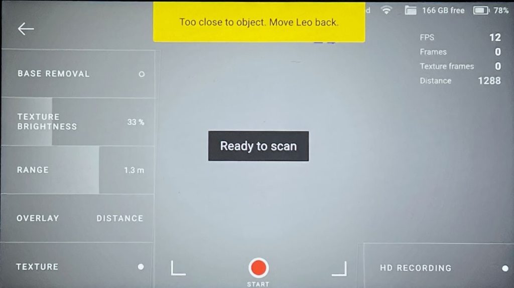
Above we can see the image on the Artec Leo 3D scanner when you are to start a new scan job. There are several options that I will explain and you’ll get a better idea of how it operates.
Base Removal: This feature tells the scanner to discard the “base”. Usually this means the floor or table on which the subject is positioned. This is a bit of a shortcut as normally you’d clip off that segment during post-capture processing.
Texture Brightness: This tells the scanner how bright the captured texture should be. The choice depends on whether the texture is important. If you’re just capturing a geometry of a part, then it can be low.
Range: This value determines how far away the scanner’s range will be during this scan job. Typically it’s set to ensure you keep close enough to capture a sufficient amount of detail. If you’re farther away, there is less detail in the capture.
Overlay or Distance: This is an interesting feature that tells the display how to operate during scanning. Distance will give you a “red or green” depending on your optimal distance from the subject. I like that mode because then my job as the operator is to simply slide that sweet green zone over top of all surfaces.
HD Recording: This is a special feature that allows far greater detail in the capture. If you tick this box, then that data is captured. However, there’s a caveat: you must have a powerful laptop on the other end to process it. I attempted to do several HD captures, and while I captured objects, I was unable to process them on the provided laptop, an HP ZBook 15, [email protected], 64GB, Quadro M 1000M. Well, perhaps they may have finished eventually, but processing was certainly too long to be practical.
Artec Leo Capture Processing
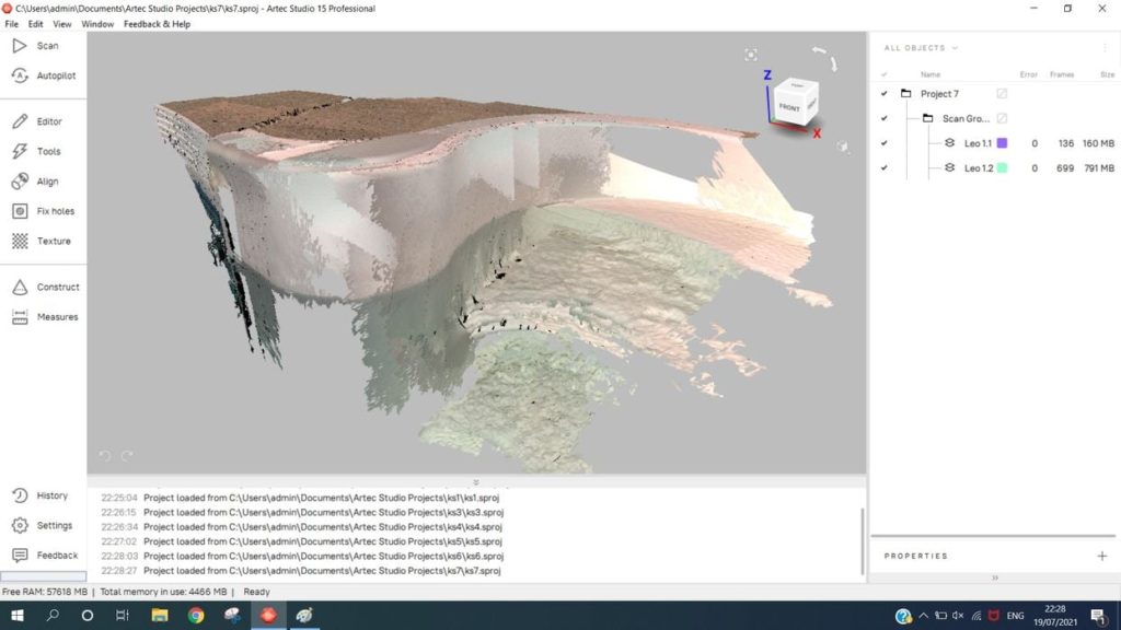
After all the fun of capturing objects, the less exciting job of processing the data takes place. This is usually done back at a desk, where you can let the machine run for longer periods. You’ll be using Artec Studio, a powerful tool. Currently it’s at release 15.
It might be a good idea to capture objects more than once in the field, especially if you are not processing them on site. If you missed something, then it would be a good idea to have another scan in your pocket. The Artec Leo operates so swiftly it’s not that much trouble to get another scan while you’re set up on site, and it could save a lot of trouble afterwards. Even better, there are ways to join separate scans of the same object together.
The first step in processing is to transfer the scan from the handheld unit to the laptop. There are a couple of ways of doing so, but the recommended approach is to use a standard Ethernet cable between scanner and laptop. It’s a straightforward method that’s easy to trigger.
And it’s also quite fast. The scans are of considerable size, because they are comprised of a mix of scan and texture images. While it’s not an instant transfer, I never waited very long for transfers to complete.
Once the scan is loaded into Artec Studio, there are many ways to proceed, as the software is quite flexible. Generally, however, the workflow I went through was something like this:
Rough Registration: This step takes all the captured frames and attempts to make sense of them. They’ve been taken from many different orientations, and initially you may see your model “messed up”, as the preview may have gotten confused about some of the frames.
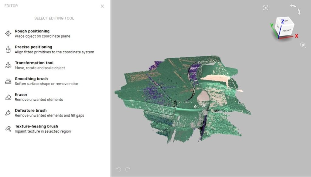
Editing: Once the capture makes more sense, this is the step I take to remove clutter and surfaces that are not required. If you haven’t automatically removed the floor, this is where you do that. Artec Studio has a large number of editing tools to do practically anything you can imagine on the capture. I used only a very few of them, and I can see how they would be useful for more complex projects.
Global Registration: After I’ve cleaned up the capture, I like to another registration to ensure all frames are properly lined up.
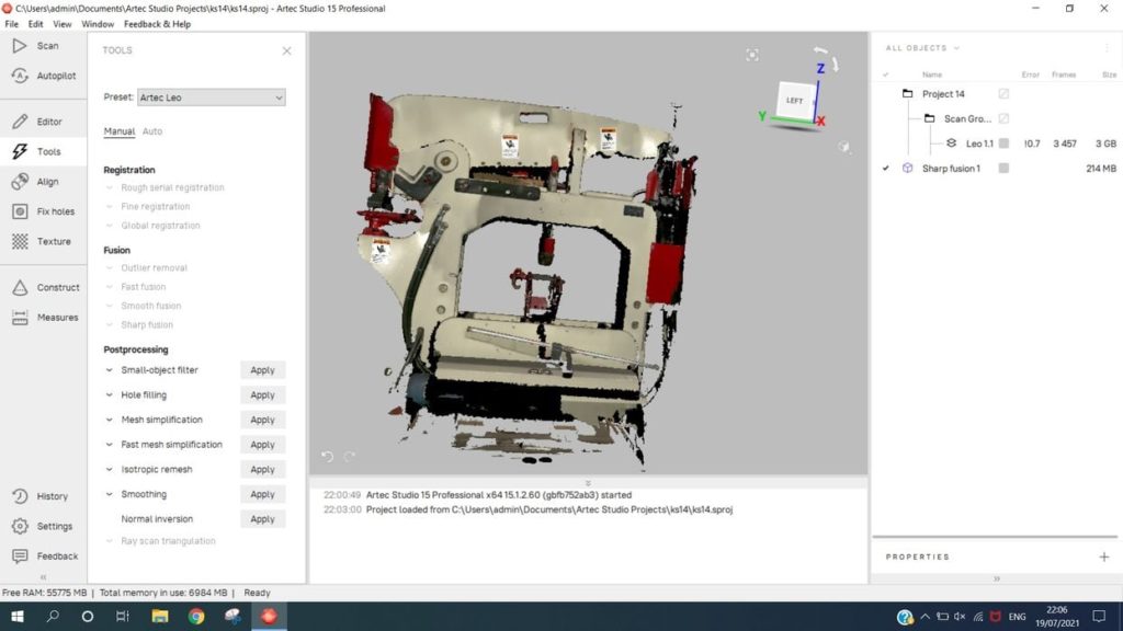
Fusion: This step is where the real action takes place. Up to now, the capture is simply a pile of images. Here we “fuse” the computed point cloud into a proper mesh. Artec Studio offers a couple of different styles of meshing. For mechanical part 3D scans I would use “Sharp Fusion”, which expects to see items with flat surfaces and sharp corners. Alternatively you could use “Smooth Fusion” for more organic surfaces, like sculptures or people. Surprisingly, this step doesn’t take that long to complete.
Mesh Simplification: Once the mesh is created it contains all the detail from the capture. That’s often far more than is required. For example, if you scan a book you would have a very slightly bumpy surface on the otherwise flat book. This is due to natural accuracy limitations of the hardware. As a result the “flat” surface of the book will be bumpy, and that “detail” generates a great deal of mesh triangles.
To overcome this you must almost always simplify the mesh. It’s a straightforward matter where you specify how many polygons you want to get, and Artec Studio quickly gets it done.
Texturing: The final step is texturing. This is not necessary for mechanical parts, but was for many of the items I scanned. The process is to imprint a color texture on each surface of the 3D mesh based on the color images taken intermittently during the capture process.
Of all the steps required in the processing, this was by far the heaviest. For this I often would wander away and do something else while texturing took place, to give you an idea of how long it took. Of course, the time required depends entirely on the complexity of the 3D model.

There’s one other step I tried that could be quite useful in some scenarios: Alignment. This allows you to take more than one scan of a subject and then paste them together to form a larger scan in post-processing. Typically you’d do this when capturing a larger object, like a car. You’d do a fender, then another fender, then the front, etc.
Another scenario where this could be useful if you have an object where the bottom needs to be scanned as well as the top. It’s a simple matter of scanning once, then turning the item upside down and scanning again.
Alignment is done by importing all the related scans into Artec Studio and launching the Alignment tool. The process is straightforward: just identify at least three points on each capture that represent the same spot on the subject, then pair them together. Then, as if by magic, the multiple captures align into a fully complete object. It’s pretty amazing to watch.
This is part 2 of a 3 part series. Please read part 1 and part 3.
Via Artec 3D