
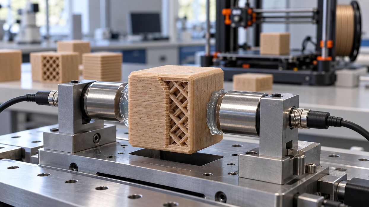
A new ultrasonic test method reveals how strongly infill geometry controls the stiffness of FFF printed wood PLA parts.
FFF operators already know that a test coupon can’t tell you everything about the strength of a material or parts made from that material. A part may perform well when pulled along its extrusions, then flex far more easily across them. That directional behavior, known as anisotropy, is a constant issue when designing load bearing printed parts.
Researchers from laboratories in Le Havre, France, and Sfax, Tunisia, tackled that problem with PLA and PLA loaded with wood flour, commonly known as “Wood PLA”. Instead of testing a few coupons in tension, they used ultrasonic waves through specially shaped cubic specimens to calculate the complete orthotropic elastic tensor.
An orthotropic material has different elastic behavior along three perpendicular axes, which is a much closer description of a real FFF part than treating it as a uniform plastic block.
Nine Stiffness Values Without Destroying The Part
The team printed 72 chamfered cubes across 24 process configurations, with three replicates per configuration. They varied layer thickness, infill density, infill pattern, and whether the material was plain PLA or PLA wood flour composite.
Ultrasound measurements along three directions and three face diagonals provided the nine independent stiffness coefficients needed for the tensor. Reported repeatability within each configuration ranged from 1.2% to 6.2%, a respectable result for a non destructive method examining a structure full of extrusions, voids, and interlayer boundaries.
For production 3D printing, this could be quite interesting. A manufacturer could potentially inspect a printed component or qualification sample without destroying it in a tensile testing rig. The method is only research at this point, and not something you could buy for your workshop, but it presents a possible way to build such a thing. It could also suggest it may be possible to improve material specifications for simulation and more realistic design rules.
Infill Pattern Was The Dominant Lever
The strongest result was about the infill pattern. At low infill density, the Line pattern produced an in plane stiffness ratio, E2/E1, as high as 2.9. In other words, a part was almost three times stiffer in one horizontal direction than the perpendicular one.
The Combined pattern, by comparison, produced near unity ratios, meaning much more balanced in plane stiffness. If you are printing brackets, panels, or fixtures where loads can show up from any direction, that is likely more important than a single tensile strength figure printed on a material spool.
Wood flour also did something more interesting than just change the overall modulus. At low density, it preferentially redistributed stiffness transverse to the filaments. The researchers measured recovery of E1 by up to 110% and reductions in in plane anisotropy of up to 41%.
Acoustic microscopy suggests a possible reason for this: wood flour may bridge spaces between adjacent extrusions.
But the Z direction remained softer regardless of direction. No amount of pattern selection removes the usual FFF weakness at each layer. Structural designers would still need to orient parts around the expected load path, control thermal conditions, and validate bonding for the specific machine and filament.
The paper also reports an apparent near zero and slightly negative Poisson’s ratio, down to -0.06, in one low density Line configuration.
For FFF materials providers, a full directional stiffness map might eventually become a better sales and engineering tool than a single tensile number.
Via IOPscience